Mechanical automatic stop device of wire coil machine

A wire reel machine, mechanical technology, applied in the direction of transportation and packaging, delivery of filamentous materials, thin material processing, etc., can solve the problems of early warning of production conditions, product waste, economic loss, etc., to prevent the stop speed from being too slow, Easy to use, safe and reliable operation

Active Publication Date: 2020-02-28
泰州市赛鸥网业有限公司
View PDF10 Cites 16 Cited by
  • Summary
  • Abstract
  • Description
  • Claims
  • Application Information

AI Technical Summary

Problems solved by technology

[0002] After the cable is produced, it is usually necessary to wrap the large roll of cable on a small reel according to the needs of the customer. This work needs to be done with a reel machine. During the winding process, the reel machine will Uncoordinated running speed or equipment failure causes the cable to be broken or tangled during the winding process. These situations not only delay the production efficiency, but also cause product waste and bring certain economic losses to the company. If the line The reel machine can stop the winding in time before these situations occur, so as to avoid the excessive pulling of the cable and reduce the production of defective products. The situation is early warning, the stop is not fast enough, there is no safety protection measure, and the cable length needs to be measured with the help of external equipment, which is poor in practicability. Therefore, we propose a mechanical automatic stop device for the reel machine to solve the above defects

Method used


Image

  • Mechanical automatic stop device of wire coil machine
  • Mechanical automatic stop device of wire coil machine
  • Mechanical automatic stop device of wire coil machine

Examples


Embodiment Construction

[0027] The following will clearly and completely describe the technical solutions in the embodiments of the present invention with reference to the accompanying drawings in the embodiments of the present invention. Obviously, the described embodiments are only some, not all, embodiments of the present invention. Based on the embodiments of the present invention, all other embodiments obtained by persons of ordinary skill in the art without making creative efforts belong to the protection scope of the present invention.

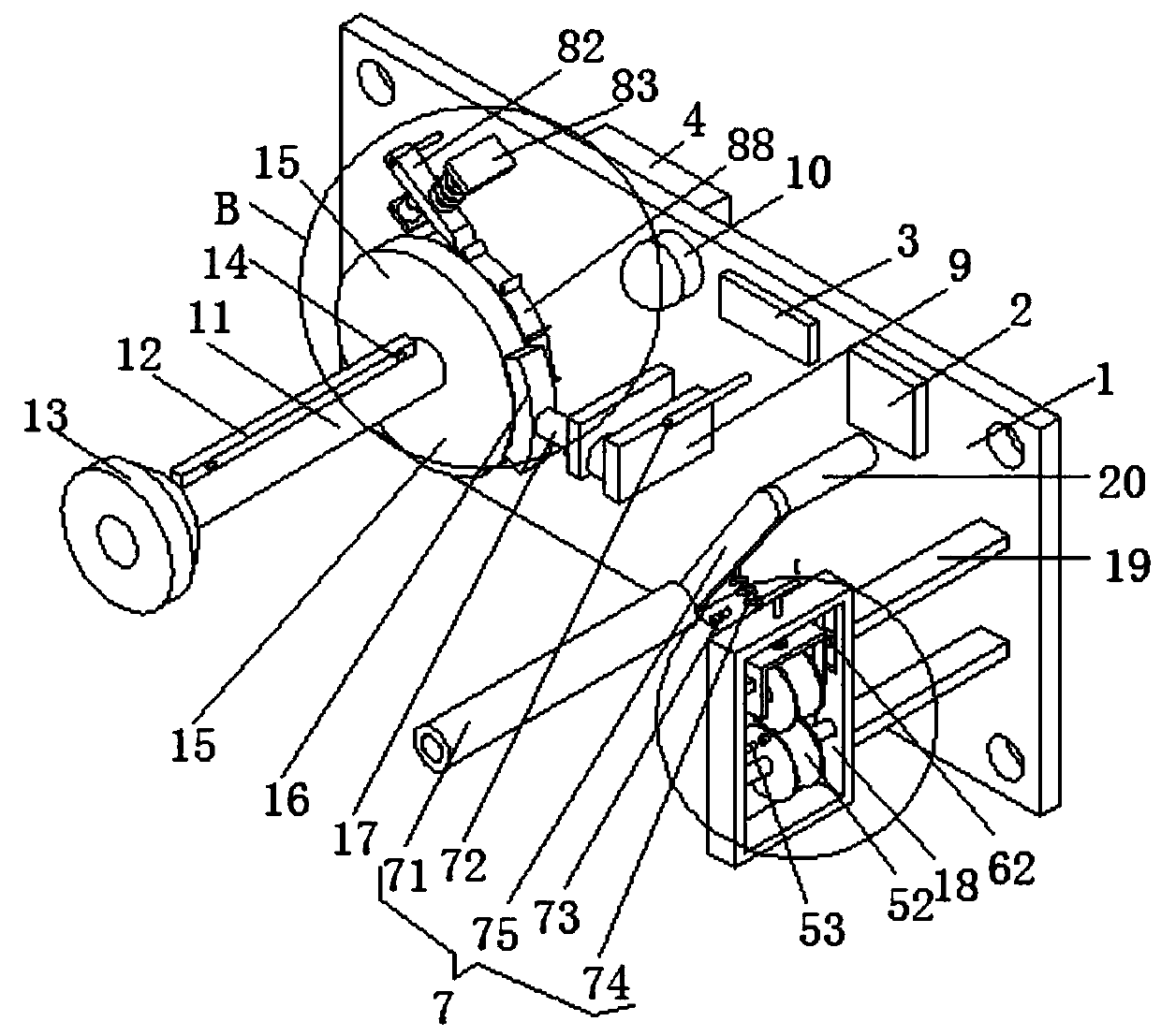
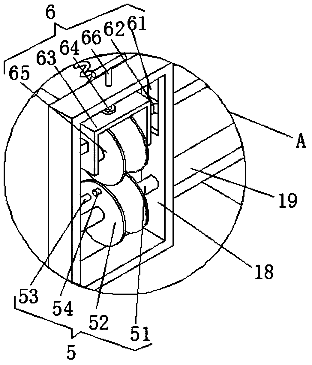
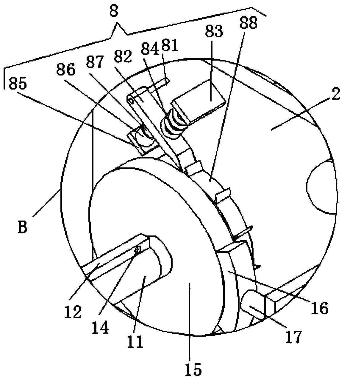
[0028] see Figure 1-3 , the present invention provides a technical solution: a mechanical automatic stop device for a reel machine, comprising a mounting plate 1, a length measurement unit 5, a pressing unit 6, an abnormality detection unit 7 and an emergency stop unit 8;

[0029] Mounting plate 1: The motor 4 is fixedly connected to the rear side of the mounting plate 1, the output shaft of the motor 4 passes through the through hole of the mounting plate 1,...


PUM


Abstract

The invention discloses a mechanical automatic stop device of a wire coil machine. The mechanical automatic stop device comprises a mounting plate, a length measuring unit, a pressing unit, an abnormity detecting unit and an emergency stop unit, wherein the back side surface of the mounting plate is fixedly connected with a motor; an output shaft of the motor penetrates through a through hole of the mounting plate; the front end of the output shaft of the motor is fixedly connected with a mounting shaft; the back end of the outer arc surface of the mounting shaft is fixedly connected with a brake disc; the middle part of the front side surface of the mounting plate is fixedly connected with a third fixed plate; the left side surface of the third fixed plate is fixedly connected with an electric push rod; the left end of the electric push rod is fixedly connected with a brake pad; the brake pad is of an arc structure; the inner arc surface of the brake pad is corresponding to the outerarc surface of the brake disc; and the back end of the front side surface of the mounting plate is fixedly connected with a support plate. The mechanical automatic stop device of the wire coil machineis novel in structure, needs no external equipment to measure the length of a cable, can automatically take corresponding stop measures according to different conditions, and is high in safety and convenient to operate.

Description

technical field [0001] The invention relates to the technical field of wire reel machines, in particular to a mechanical automatic stop device for wire reel machines. Background technique [0002] After the cable is produced, it is usually necessary to wrap the large roll of cable on a small reel according to the needs of the customer. This work needs to be done with a reel machine. During the winding process, the reel machine will Uncoordinated running speed or equipment failure causes the cable to be broken or tangled during the winding process. These situations not only delay the production efficiency, but also cause product waste and bring certain economic losses to the company. If the line The reel machine can stop the winding in time before these situations occur, so as to avoid the excessive pulling of the cable and reduce the production of defective products. The situation is early warning, the stop is not fast enough, there is no safety protection measure, and the ...

Claims


Application Information

Patent Timeline
Patent Type & Authority Applications(China)
IPC IPC(8): B65H61/00B65H63/04B65H63/00B65H57/14B65H59/10B65H63/06
CPCB65H57/14B65H59/10B65H61/00B65H63/00B65H63/04B65H63/065B65H2701/34
Inventor 张大涌
Owner 泰州市赛鸥网业有限公司
Why Eureka
Try Eureka