Supercharge Your Innovation With Domain-Expert AI Agents!

A method for measuring the complex cross-polarization ratio using two identical antennas under test

A measurement method, co-polarization technology, applied in the direction of antenna radiation pattern, etc., can solve the problems of high cost, great influence on measurement accuracy, increased measurement difficulty and measurement system complexity, so as to reduce difficulty and cost, and reduce test The effect of reducing the error and reducing the difficulty of realization

Active Publication Date: 2020-11-03
SOUTHEAST UNIV
View PDF14 Cites 0 Cited by
  • Summary
  • Abstract
  • Description
  • Claims
  • Application Information

AI Technical Summary

Problems solved by technology

[0003] In this existing antenna cross-polarization ratio measurement method, when the cross-polarization ratio of the reference antenna is higher than that of the antenna under test, the cross-polarization ratio of the antenna under test cannot be accurately measured.
If the cross-polarization performance of the antenna under test is excellent, it is difficult to find a reference antenna with a smaller cross-polarization than the antenna under test in the same frequency band, and its cost is also high, which increases the difficulty of measurement and the complexity of the measurement system.
At the same time, when the cross-polarization of the antenna under test is small, the imperfection of the darkroom environment and the measurement device will have a great impact on the measurement accuracy

Method used


Image

  • A method for measuring the complex cross-polarization ratio using two identical antennas under test
  • A method for measuring the complex cross-polarization ratio using two identical antennas under test
  • A method for measuring the complex cross-polarization ratio using two identical antennas under test

Examples


Embodiment Construction

[0034] The specific implementation manners of the present invention will be further described below in conjunction with the drawings and examples.

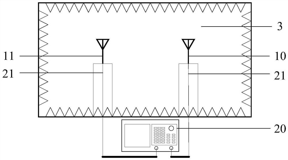
[0035] exist figure 1 Among them, the structure of the measurement system using the complex cross-polarization ratio of two identical antennas under test consists of a first antenna under test 10 and a second antenna under test 11 , a measuring instrument 20 and a cable 21 . The structure and performance of the first antenna under test 10 and the second antenna under test 11 are completely the same. The test was carried out in microwave anechoic chamber 3. The specific implementation of the method for measuring the complex cross-polarization ratio of two identical antennas to be tested is divided into three steps:

[0036] Step 1 Installation of the first antenna to be tested 10 and the second antenna to be tested 11:

[0037] The first antenna under test 10 and the second antenna under test 11 are respectively fixed, and the f...


PUM


Abstract

The invention discloses a method for measuring a complex cross polarization ratio by using two identical to-be-measured antennas, and relates to a method for measuring the cross polarization ratio ofan antenna. A first to-be-measured antenna (10) and a second to-be-measured antenna (11) which have the same structure and performances, a measuring instrument (20) and a cable (21) are used. A test is carried out in a microwave anechoic chamber (3). The first to-be-measured antenna (10) and the second to-be-measured antenna (11) are arranged in a far field area; the measuring instrument (20) is connected to the first to-be-measured antenna and the second to-be-measured antenna through the cable (21); the second to-be-measured antenna is used as a receiving antenna, a plurality of attenuationfactors are acquired during polarization matching and polarization orthogonality, and a plurality of cross polarization ratios of the second to-be-measured antenna are calculated according to the attenuation factors; the to-be-measured antennas are taken as receiving antennas, the complex cross polarization ratio of the first to-be-measured antenna is measured, and a measurement value of the complex cross polarization ratio through averaging. According to the method, a reference antenna is omitted, the measurement is simplified, and errors caused by the environment are reduced through multiple times of measurement.

Description

technical field [0001] The invention relates to an antenna measurement method, in particular to a measurement method using the cross polarization ratio of two identical antennas to be tested. Background technique [0002] As a parameter of the antenna, the cross-polarization ratio plays a key reference role in the application design of multiple-input multiple-output antenna arrays, dual-polarized antennas, and polarization multiplexing systems. Measuring the antenna cross-polarization ratio is a non-negligible step when measuring antennas with high polarization isolation. But in the actual antenna measurement, the antenna with low cross-polarization ratio is difficult to measure accurately due to the small cross-polarization component. Existing cross-polar ratio measurement methods require a reference antenna. In order to ensure measurement accuracy, the cross-polarization ratio of the reference antenna is required to be much lower than that of the antenna under test. [...

Claims


Application Information

Patent Timeline
Patent Type & Authority Patents(China)
IPC IPC(8): G01R29/10
CPCG01R29/10
Inventor 李顺礼张遒逸赵洪新
Owner SOUTHEAST UNIV
Features
  • R&D
  • Intellectual Property
  • Life Sciences
  • Materials
  • Tech Scout
  • Unparalleled Data Quality
  • Higher Quality Content
  • 60% Fewer Hallucinations
Learn More