Wiring device for power construction

A wiring device and power construction technology, applied in circuits, connections, electrical components, etc., can solve the problems of low work efficiency, large workload, and unfavorable conductive efficiency of wires, and achieve good wiring effect, fast wiring speed, and mutual articulation process. Smooth and unobstructed effect

Active Publication Date: 2020-02-28
江苏和动力电子工程有限公司
View PDF5 Cites 2 Cited by
  • Summary
  • Abstract
  • Description
  • Claims
  • Application Information

AI Technical Summary

Problems solved by technology

[0002] In order to extend the length of wires or form many useful parallel circuits in electric power construction, splicing work between wires is essential, and the workload is huge; Splicing operation, the operation process is cumbersome, and the work efficiency is low; in the process of splicing the wires with tools, it is easy to scratch or deform the splicing of the wires, thereby reducing the service life of the wires and It is not conducive to the conductive efficiency of the wire; in the process of splicing the wire with traditional tools, due to the poor grasp of the strength, it is easy to damage and break the exposed copper core after the wire is peeled, thereby causing damage to the wire and reducing the wiring work. efficiency

Method used


Image

  • Wiring device for power construction
  • Wiring device for power construction
  • Wiring device for power construction

Examples


Embodiment Construction

[0037] The accompanying drawings are all schematic diagrams of the implementation of the present invention, so as to understand the principle of structural operation. The specific product structure and proportional size can be determined according to the use environment and conventional technology.

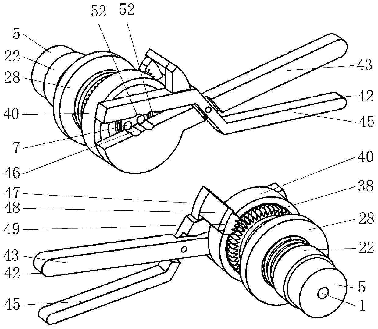
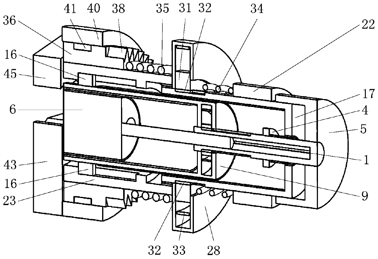
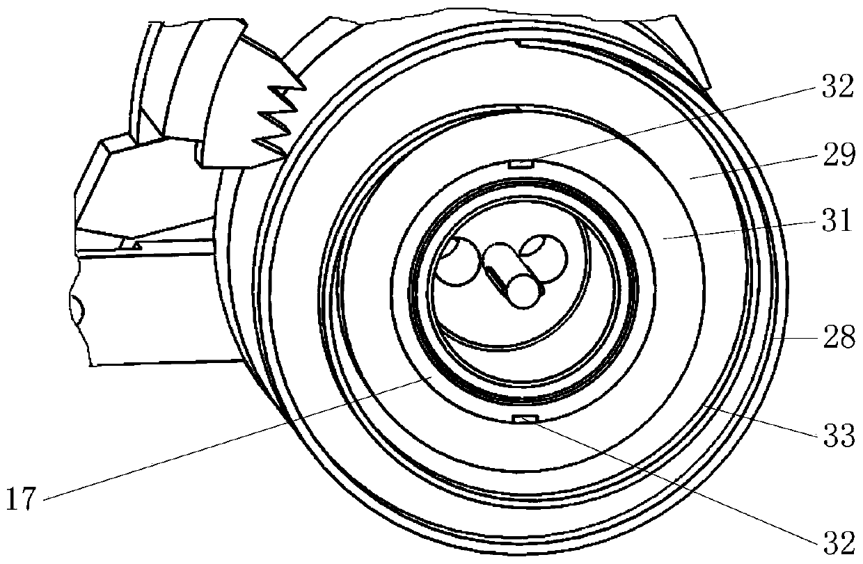
[0038] Such as figure 1 , 2 , 10, it includes telescopic shaft 1, ring A4, twist wheel 5, strand post 6, strand hole 7, drum A9, ring B13, scroll spring A15, drum B17, ring C22, cylindrical tube 23. Ring D28, ring groove D29, circular groove 30, ring E31, scroll spring B33, return spring A34, return spring B35, ring F36, limit tooth A38, ring G40, clamping mechanism 42, among which Figure 5 As shown, the internal thread A11 on the inner cylinder of the barrel A9 is threaded with the external thread B8 on the outer cylinder of the strand post 6; Figure 5 , 15 As shown, the outer shaft of the telescopic shaft 1 rotates and slides in the circular hole at the bottom center of th...


PUM


Abstract

The invention belongs to the field of power construction wiring, and particularly relates to a wiring device for power construction, which includes a telescopic shaft, a twisting post, a barrel A, anda clamping mechanism, wherein the internal threads A on the inner cylindrical surface of the barrel A match the external threads B thread on the outer cylindrical surface of the twisting post. In order to prevent the exposed copper core of a wire from being damaged by the twisting post with a low axial movement speed during a twisting process, a cylindrical barrel moves away from the wire in theaxial direction of the telescopic shaft relative to a ring F under the interaction between the twisting post and a twisted copper core, and moves all parts matching the cylindrical barrel synchronously to compensate for the axial movement speed of the telescopic shaft in the axial direction of the telescopic shaft, thereby increasing the movement speed of the twisting post and thus minimizing thesqueezing and scratching of the twisted parts of two wires caused by the low axial speed of the rotating twisting post, and reducing, to a certain extent, the physical effort required to twist thickerwires, wherein the movement of the twisting post avoids the breakage of the twisted parts of the two wires due to excessive force.

Description

technical field [0001] The invention belongs to the field of electric power construction wiring, and in particular relates to a wiring device used in electric power construction. Background technique [0002] In order to extend the length of wires or form many useful parallel circuits in electric power construction, splicing work between wires is essential, and the workload is huge; Splicing operation, the operation process is cumbersome, and the work efficiency is low; in the process of splicing the wires with tools, it is easy to scratch or deform the splicing of the wires, thereby reducing the service life of the wires and It is not conducive to the conductive efficiency of the wire; in the process of splicing the wire with traditional tools, due to the poor grasp of the strength, it is easy to damage and break the exposed copper core after the wire is peeled, thereby causing damage to the wire and reducing the wiring work. efficiency. [0003] The present invention des...

Claims


Application Information

Patent Timeline
Patent Type & Authority Applications(China)
IPC IPC(8): H01R43/033
CPCH01R43/033
Inventor 石鑫
Owner 江苏和动力电子工程有限公司
Why Eureka
Try Eureka