Power transmission line deicing device

A technology for transmission lines and cleaning devices, which is applied in the installation of cables, overhead installation, electrical components, etc., can solve the problems of time-consuming and labor-intensive, threatening the stable operation of the power grid, and high danger, and achieve the effect of convenient use and efficient ice-breaking treatment.

Inactive Publication Date: 2020-02-28
STATE GRID CORP OF CHINA +3
View PDF6 Cites 5 Cited by
  • Summary
  • Abstract
  • Description
  • Claims
  • Application Information

AI Technical Summary

Problems solved by technology

[0003] The power transmission lines are basically in the outdoor environment. In the rainy and snowy weather in winter, the transmission lines will be covered with snow and ice. When the temperature is cold enough, the surface of the power supply cable will freeze, and the ice will increase the cable The overall weight is prone to danger. The icing of the line not only greatly threaten

Method used


Image

  • Power transmission line deicing device
  • Power transmission line deicing device
  • Power transmission line deicing device

Examples


Embodiment 1

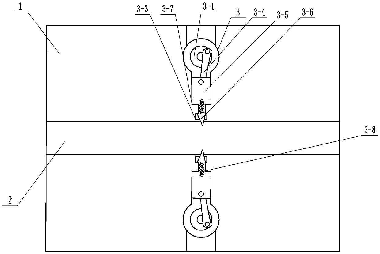
[0033] The present invention provides a deicing device for a power transmission line, which includes a housing 1 , an inlet channel 2 passing through the housing 1 , an ice breaker 3 arranged in the housing 1 , and the ice breaker 3 Located on the upper and lower sides of the wire inlet channel 2, the ice breaker 3 is perpendicular to the wire inlet channel 2.

[0034] The ice breaker 3 includes a turntable 3-1 rotatably arranged on the housing 1, a connecting rod 3-4, a first guide rail 3-7, a second guide rail 3-3 communicating with the first guide rail 3-7, The push block 3-5 arranged in the first guide rail 3-7 and adapted to the first guide rail 3-7 is arranged in the second guide rail 3-3 and matched with the second guide rail 3-3 Compatible ice skates 3-6; one end of the connecting rod 3-4 is rotatably connected to the disc body of the turntable 3-1, and the other end of the connecting rod 3-4 is hinged with the push block 3-5, so The other end of the push block 3-5 is...

Embodiment 2

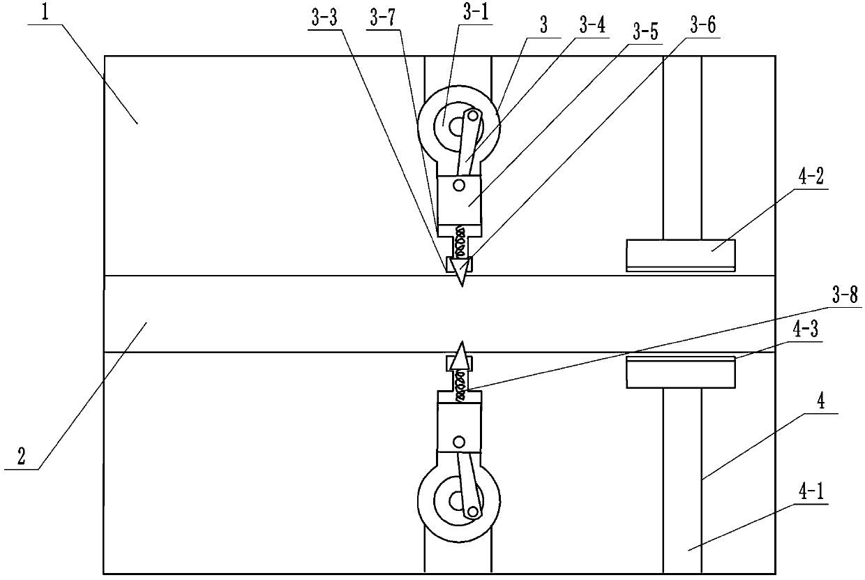
[0038]The present invention provides a deicing device for a power transmission line, which includes a housing 1 , an inlet channel 2 passing through the housing 1 , an ice breaker 3 arranged in the housing 1 , and the ice breaker 3 Located on the upper and lower sides of the wire inlet channel 2, the ice breaker 3 is perpendicular to the wire inlet channel 2.

[0039] The ice breaker 3 includes a turntable 3-1 rotatably arranged on the housing 1, a connecting rod 3-4, a first guide rail 3-7, a second guide rail 3-3 communicating with the first guide rail 3-7, The push block 3-5 arranged in the first guide rail 3-7 and adapted to the first guide rail 3-7 is arranged in the second guide rail 3-3 and matched with the second guide rail 3-3 Compatible ice skates 3-6; one end of the connecting rod 3-4 is rotatably connected to the disc body of the turntable 3-1, and the other end of the connecting rod 3-4 is hinged with the push block 3-5, so The other end of the push block 3-5 is ...

Embodiment 3

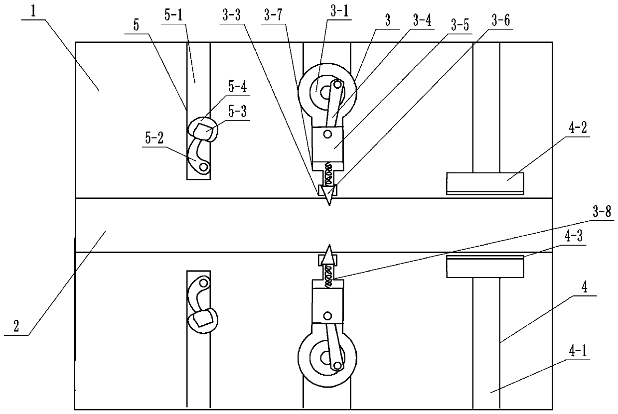
[0044] The present invention provides a deicing device for a power transmission line, which includes a housing 1 , an inlet channel 2 passing through the housing 1 , an ice breaker 3 arranged in the housing 1 , and the ice breaker 3 Located on the upper and lower sides of the wire inlet channel 2, the ice breaker 3 is perpendicular to the wire inlet channel 2.

[0045] The ice breaker 3 includes a turntable 3-1 rotatably arranged on the housing 1, a connecting rod 3-4, a first guide rail 3-7, a second guide rail 3-3 communicating with the first guide rail 3-7, The push block 3-5 arranged in the first guide rail 3-7 and adapted to the first guide rail 3-7 is arranged in the second guide rail 3-3 and matched with the second guide rail 3-3 Compatible ice skates 3-6; one end of the connecting rod 3-4 is rotatably connected to the disc body of the turntable 3-1, and the other end of the connecting rod 3-4 is hinged with the push block 3-5, so The other end of the push block 3-5 is...


PUM


Abstract

The invention relates to a power transmission line deicing device, which comprises a shell, a wire inlet channel penetrating through the shell, and ice breakers arranged in the shell and perpendicularto the wire inlet channel and distributed on the upper side and the lower side of the wire inlet channel. Each ice breaker comprises a rotary disc rotationally arranged on the shell, a connecting rod, a first guide rail, a second guide rail communicated with the first guide rail, a push block arranged in the first guide rail and matched with the first guide rail, and an ice knife arranged in thesecond guide rail and matched with the second guide rail, wherein one end of the connecting rod is rotationally connected to a disc body of the rotary disc, the other end of the connecting rod is hinged to the push block, the other end of the push block is connected with the ice knife, and the rotary disc is driven by a first motor. The power transmission line deicing device can effectively deicea power transmission line.

Description

technical field [0001] The invention relates to the technical field of electric power equipment, and in particular, the invention relates to a deicing device for a power transmission line. Background technique [0002] The power transmission line is a conductor circuit that connects the substation and distribution station with various electric energy users or electric equipment, and transmits and distributes electric energy from the power source (transformation and distribution station) to the load end (electric energy user or electric equipment). [0003] The power transmission lines are basically in the outdoor environment. In the rainy and snowy weather in winter, the transmission lines will be covered with snow and ice. When the temperature is cold enough, the surface of the power supply cable will freeze, and the ice will increase the cable The overall weight is prone to danger. The icing of the line not only greatly threatens the stable operation of the power grid, but...

Claims


Application Information

Patent Timeline
IPC IPC(8): H02G7/16
CPCH02G7/16
Inventor 刘向阳张磊李朝士刘国栋李芳芳
Owner STATE GRID CORP OF CHINA
Why Eureka
Try Eureka