
Annular buffer self-adaptive network-on-chip router

An on-chip network and ring buffer technology, applied in the electronic field, can solve problems such as resource waste and system resources cannot be fully utilized, and achieve the effect of reducing message delay and improving network performance

Inactive Publication Date: 2020-02-28
石门依云电子商务有限公司
View PDF1 Cites 0 Cited by
  • Summary
  • Abstract
  • Description
  • Claims
  • Application Information

AI Technical Summary

Problems solved by technology

[0002] A chip with a network-on-chip (NOC) structure is connected with various routers in the chip network through dedicated signal lines by various embedded cores, and selects the path of data packets. These embedded cores can be DSP, processor, memory, Peripheral controllers and commonly used logic devices, etc., in the current network-on-chip system, system resources cannot be fully utilized, resulting in a great waste of resources. One of the most hungry resources in the network-on-chip is the routing buffer. Moreover, a The area occupied by the on-chip router is mainly the area of ​​the routing buffer. Therefore, in the process of building a high-performance and resource-saving system-on-chip, the design of the buffer structure plays a key role.
[0003] In order to achieve a high communication rate, the system can efficiently utilize all buffer resources, a router with a new buffer structure is proposed based on the 2D Mesh topology, and the router can dynamically adjust the buffer depth according to the communication requirements of the network to achieve Mutual sharing of channel buffer resources. Although it is proposed based on the 2D Mesh topology and the corresponding performance evaluation is carried out, the router structure is still applicable to other topologies as long as there is a deadlock-free routing algorithm as a guarantee.

Method used


Image

  • Annular buffer self-adaptive network-on-chip router

Examples


Embodiment Construction

[0015] The present invention will be further described below in conjunction with the accompanying drawings.

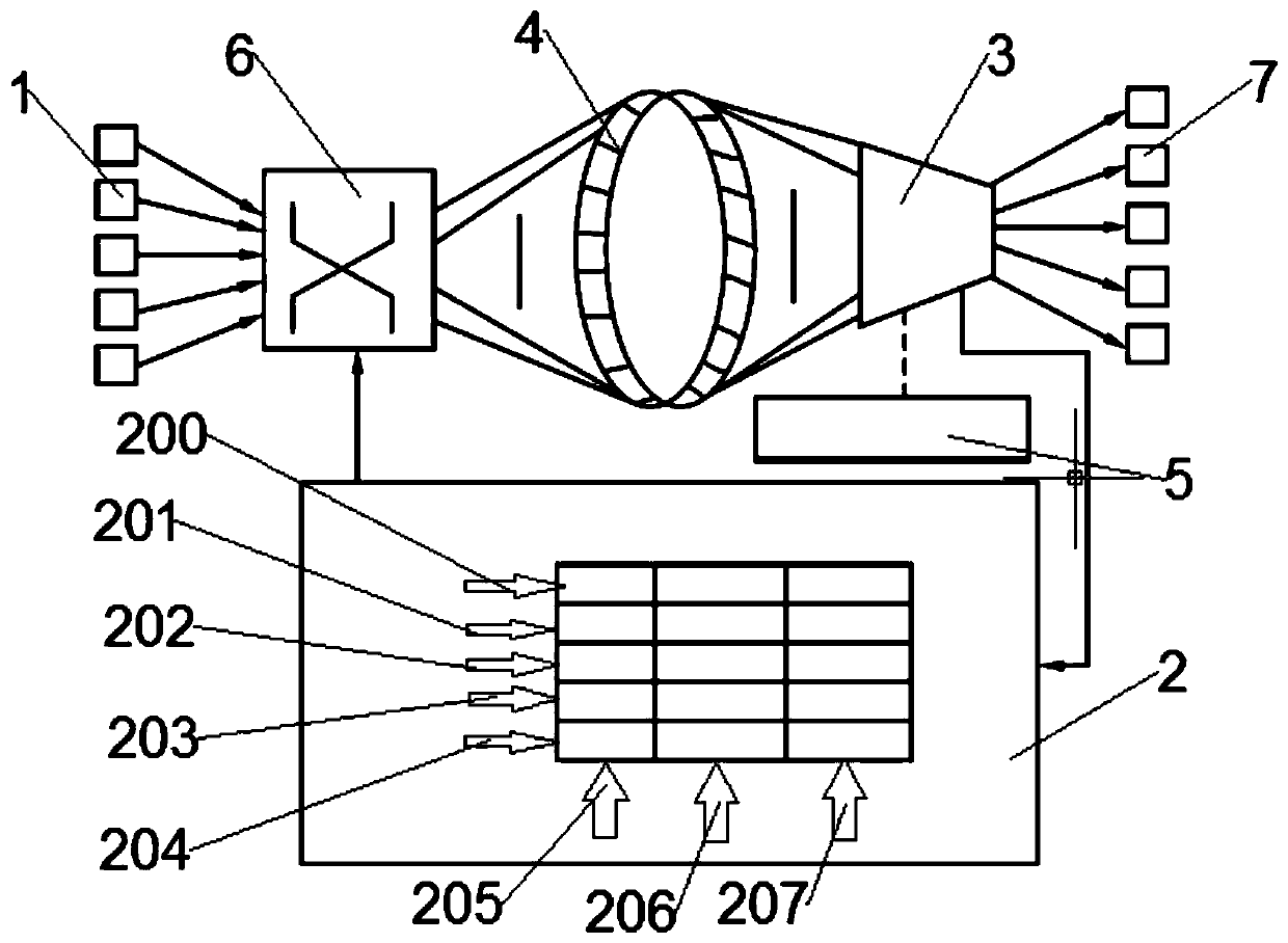
[0016] like figure 1 As shown, a ring buffer adaptive network-on-chip router according to the present invention includes an input channel 1, a buffer management register group 2, a data selector 3, a ring buffer 4, a data packet decoder 5, and a crossbar switch matrix 6 and output channel 7, the input channel 1 and output channel 7 are provided with 5, the input channel 1 is connected with the ring buffer 4 through the crossbar matrix 6, and the ring buffer 4 is connected with the output channel 7 through the data selector 3 , the buffer resources in the input channel 1 and the output channel 7 form a ring with each other, and the data selector 3 is connected to the crossbar switch matrix 6 through the buffer management register group 2 .

[0017] Further, the buffer management register group 4 is divided into five rows and three columns, the five rows are divided int...


PUM


Abstract

The invention relates to the technical field of electronics. The utility model relates to a router, in particular to an annular buffer self-adaptive network-on-chip router. The router comprises an input channel, a buffer management register group, a data selector, an annular buffer, a data packet decoder, a crossbar switch matrix and an output channel, the number of the input channels and the number of the output channels are both five. The input channel is connected with the annular buffer through the crossbar switch matrix; the annular buffer is connected with the output channel through thedata selector; buffer resources in the input channel and the output channel mutually form a ring; the data selector is connected with the crossbar switch matrix through the buffer management registergroup; according to the invention, the mutual sharing of cache resources of all channels in the router is realized, the router with the annular buffer structure has an obvious effect of improving thenetwork performance, and the router with the annular buffer structure can effectively reduce the delay of messages when experiencing heavy and medium network communication and even when the network load starts to be close to saturation.

Description

technical field [0001] The invention relates to the field of electronic technology, in particular to a ring buffer adaptive on-chip network router. Background technique [0002] A chip with a network-on-chip (NOC) structure is connected with various routers in the chip network through dedicated signal lines by various embedded cores, and selects the path of data packets. These embedded cores can be DSP, processor, memory, Peripheral controllers and commonly used logic devices, etc., in the current network-on-chip system, system resources cannot be fully utilized, resulting in a great waste of resources. One of the most hungry resources in the network-on-chip is the routing buffer. Moreover, a The area occupied by the on-chip router is mainly the area of ​​the routing buffer. Therefore, in the process of building a high-performance and resource-saving SoC, the design of the buffer structure plays a key role. [0003] In order to achieve a high communication rate, the system ...

Claims


Application Information

Patent Timeline
IPC IPC(8): H04L12/771H04L12/861H04L12/931H04L12/947H04L45/60
CPCH04L45/60H04L49/252H04L49/109H04L49/9005H04L49/9031
Inventor 刘伟
Owner 石门依云电子商务有限公司
Learn More