Bionic camera device and method in tunnel based on artificial intelligence

A camera device and artificial intelligence technology, applied in the direction of cleaning methods using tools, camera devices, chemical instruments and methods, etc., can solve problems such as landslides in nearby locations, time delays, and inability to accurately understand the situation in the tunnel in a timely manner, and achieve rapid judgment and response, to ensure the effect of safe operation

Active Publication Date: 2020-02-28
SHANDONG UNIV
View PDF10 Cites 4 Cited by
  • Summary
  • Abstract
  • Description
  • Claims
  • Application Information

AI Technical Summary

Problems solved by technology

[0005] 1. Generally, the camera device in the tunnel is a fixed device, which only records the construction situation on site, and can only monitor a certain fixed range, and cannot monitor the full range of conditions in the tunnel in real time and efficiently;
[0006] 2. There is a lot of dust during the construction in the tunnel, which often causes the camera screen to be blurred and reduces the definition, which brings great troubles to the monitoring personnel outside the tunnel, and cannot timely and accurately understand the situation inside the tunnel;
[0007] 3. When the surface of the camera device is covered with dust, it cannot be cleaned by itself, which brings inconvenience to the later monitoring, and the device is located at a high place, and manual cleaning also poses safety hazards;
[0008] 4. Since the camera is a fixed device, when there is a blast, the camera device cannot protect itself in time, which is likely to cause damage and unnecessary losses, and it is difficult to repair after damage and delays time;
[0009] 5. When there is a large displacement of the face in the tunnel, the camera device cannot give feedback in time, which may easily cause damage such as collapse of the face and nearby locations

Method used


Image

  • Bionic camera device and method in tunnel based on artificial intelligence
  • Bionic camera device and method in tunnel based on artificial intelligence
  • Bionic camera device and method in tunnel based on artificial intelligence

Examples


Embodiment 1

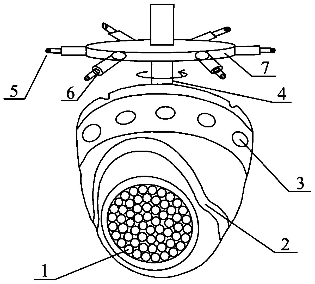
[0047] Such as figure 1 As shown, the artificial intelligence-based bionic camera device in the tunnel proposed in this implementation includes the main body of the bionic camera device, the "compound eye" camera, explosion-proof plates, indicator lights, rotating rods, distance sensor probes, elastic nodes, discs, etc.

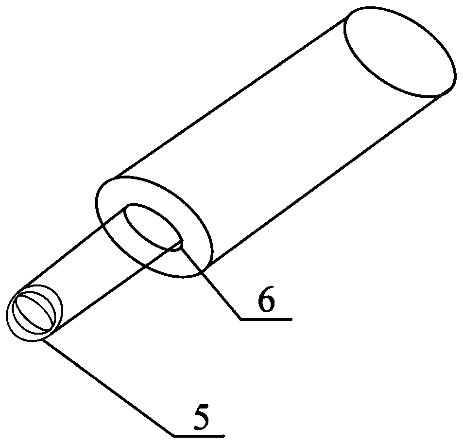
[0048] The main body of the bionic camera device is a shell, and the upper part of the shell is provided with a rotating rod 4, which can be rotated according to the control command of the remote server or the intelligent perception system for explosion-proof self-protection; At least six retractable distance sensors 5 can perform all-round real-time detection on the surroundings, and can automatically shrink when explosion-proof; of course, it is not difficult to understand that the specific number of distance sensors 5 is set according to actual requirements;

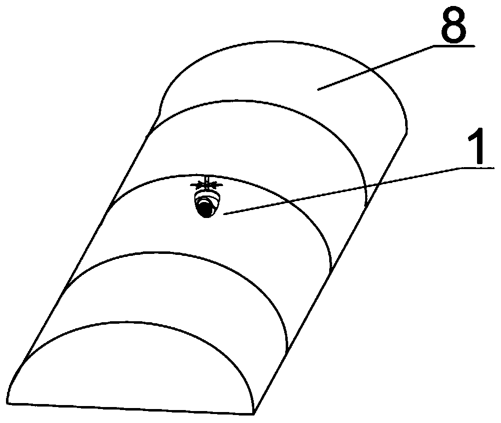
[0049] The main body of the device is equipped with a number of "compound eye" cameras 1, which c...


PUM


Abstract

The invention discloses a bionic camera device and method in a tunnel based on artificial intelligence, and the device comprises a shell which is provided with a detection system, an automatic alarm system, a control system, and a wireless transmission system. The detection system performs omnibearing real-time detection on the periphery; a plurality of compound eye cameras are arranged right in front of the shell and are used for acquiring high-definition images in the tunnel in a real-time multi-angle range; the distance sensor and the compound eye camera are both connected with the controlsystem, and the control system calculates the target body position information at each moment in real time according to the target body position information detected by the distance sensor and the compound eye camera to judge whether to start the automatic alarm system or not; and the control system transmits the in-hole construction state and the tunnel face condition shot by the bionic camera device to the remote server in real time through the wireless transmission system, and receives a control instruction of the remote server. The structural design based on bionics has the advantages of safety, high efficiency, convenience, quickness, accurate monitoring result and the like.

Description

technical field [0001] The invention relates to a bionic camera device and method in a tunnel based on artificial intelligence. Background technique [0002] With the rapid development of my country's economic construction, more and more railways, highways and subsea tunnels have begun to be built in large numbers. During the construction of the tunnel project, in order to monitor the actual situation in the tunnel in real time, digital devices such as various cameras are generally installed in the tunnel. Whether it is a railway road tunnel or a subsea tunnel, when the drilling and blasting method is used for construction, the loose gravel produced by various rock bursts or blasting will jump in all directions, causing certain damage to various facilities in the tunnel. The camera devices in the tunnel are fragile facilities and are easily damaged by the impact of the collapsed rubble. Moreover, the camera device and other functions in the complex environment in the tunne...

Claims


Application Information

Patent Timeline
Patent Type & Authority Applications(China)
IPC IPC(8): H04N7/18H04N5/225H04N5/232G08B7/06G08B21/18F16M11/04F16M11/08F16M13/02G01C11/02B08B1/00B08B1/04
CPCH04N7/181G08B7/06G08B21/18B08B1/002B08B1/04F16M13/02F16M11/08F16M11/045G01C11/02H04N23/50H04N23/51H04N23/661
Inventor 薛翊国李广坤邱道宏苏茂鑫公惠民
Owner SHANDONG UNIV
Why Eureka
Try Eureka