Eureka AIR delivers breakthrough ideas for toughest innovation challenges, trusted by R&D personnel around the world.

Millimeter wave communication system multi-beam multi-user resource allocation method

A resource allocation and communication system technology, applied in the field of multi-beam multi-user resource allocation in millimeter wave communication systems, can solve the problems of user service quality degradation, failure to consider inter-beam interference, and failure to meet user service quality, etc., to achieve high path loss , Guarantee the effect of service quality

Active Publication Date: 2020-02-28
NO 54 INST OF CHINA ELECTRONICS SCI & TECH GRP
View PDF3 Cites 4 Cited by
  • Summary
  • Abstract
  • Description
  • Claims
  • Application Information

AI Technical Summary

Problems solved by technology

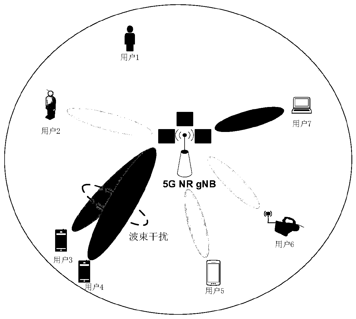
[0005] In the mmWave scenario, the current resource allocation method only solves the allocation problem of single beam to multiple users, and does not consider the allocation problem under the deployment of multiple beams by the base station, and does not consider the impact of differentiated service requirements among users on resource allocation. influences
At the same time, when the base station deploys multiple beams, the existing resource allocation method does not take into account the potential impact of inter-beam interference. When the user distribution is relatively dense, the user service quality will be greatly reduced
In addition, in the existing resource allocation methods, the method of maximizing the total user rate or proportional fairness in the system is usually adopted, which does not take into account the differentiated requirements of different services on performance indicators such as rate, delay, and packet loss rate. It can effectively reflect the degree of demand for resources and the efficiency of allocation of multi-services under each resource scheduling cycle, and thus cannot meet the quality of service of users

Method used


Image

  • Millimeter wave communication system multi-beam multi-user resource allocation method
  • Millimeter wave communication system multi-beam multi-user resource allocation method
  • Millimeter wave communication system multi-beam multi-user resource allocation method

Examples


Embodiment Construction

[0040] The present invention will be further described below in conjunction with the accompanying drawings and specific embodiments.

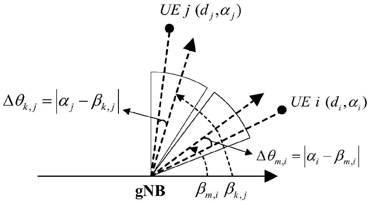
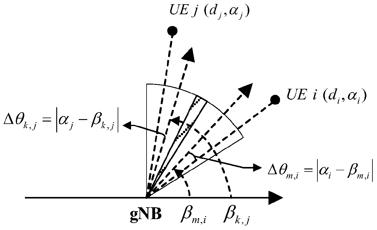
[0041] A multi-beam multi-user resource allocation method for a millimeter wave communication system, which deploys M beams on the base station in the same frequency manner, M≥2, and divides the airspace into M areas, and the beam m rotates in the area m to cover the area and serve the users in this area, 1≤m≤M; in the scheduling time slot t, first determine the users to be allocated in the beam in the first area, and then determine the users to be allocated in the beam in the next adjacent area in turn, specifically The allocation process consists of the following steps:

[0042] (1) Let m=1, then go to step (2);

[0043] (2) Determine the user to be allocated to the beam m based on the utility function, so that when the beam m is allocated to the user, the utility function of the user takes the maximum value, and then go to step (3);

[004...


PUM


Abstract

The invention discloses a millimeter wave communication system multi-beam multi-user resource allocation method, and belongs to the technical field of fifth-generation mobile communication. Accordingto the method, a plurality of wave beams are deployed on a base station in a same-frequency mode, a spatial domain is equally divided into a plurality of areas, and each wave beam rotates in the corresponding area so as to cover the area and serve users in the area; and in each scheduling time slot, to-be-allocated users of the beams in the first area are determined firstly, and then to-be-allocated users of the beams in the next adjacent region are determined in sequence. According to the method, a beam resource utility function is constructed on the basis of differentiated service requirements, user fairness, time delay and user cache, the service quality of the network can be effectively represented, and a multi-user multi-beam resource allocation optimization model is constructed by taking maximization of the utility of total network users as a target function. According to the method, efficient distribution of multiple beams is realized through two processes of beam selection anduser scheduling, and the service quality of the network can be effectively improved.

Description

technical field [0001] The present invention relates to the field of fifth-generation mobile communication technology, in particular to a multi-beam multi-user resource allocation method for a millimeter wave communication system. Background technique [0002] In order to cope with the explosive growth of mobile data traffic, massive device connections, and emerging various new services and application scenarios in the future, relying solely on the evolution of the LTE-A system can no longer meet the diverse communication needs. Therefore, the fifth generation of mobile communication ( 5G) system came into being. However, only relying on spectrum resources below 6 GHz can no longer meet the large-bandwidth and high-speed data requirements of the 5G era. Therefore, it is necessary to find new spectrum resources and fully tap the available spectrum to meet the development needs of 5G. [0003] In order to cope with the severe challenge of spectrum resource shortage, 5G system...

Claims


Application Information

Patent Timeline
Patent Type & Authority Applications(China)
IPC IPC(8): H04W72/04H04W72/08H04W72/10H04W72/54
CPCH04W72/046H04W72/541H04W72/543H04W72/542H04W72/56Y02D30/70
Inventor 郎磊张奇勋孙宇航冯志勇黄赛尉志青张轶凡王荆宁贾倩
Owner NO 54 INST OF CHINA ELECTRONICS SCI & TECH GRP
Why Eureka
Eureka Blog
Learn More