Image pick-up camera, image capture device and electronic device

A camera lens and lens technology, applied in optical components, optics, instruments, etc., can solve problems such as the inability to meet the photographic system, and achieve the effect of improving imaging quality, avoiding aberrations, and correcting high-order aberrations

Pending Publication Date: 2020-03-03
JIANGXI JINGCHAO OPTICAL CO LTD
View PDF0 Cites 0 Cited by
  • Summary
  • Abstract
  • Description
  • Claims
  • Application Information

AI Technical Summary

Problems solved by technology

[0002] Traditionally, optical systems mounted on electronic products mainly use four-piece lens structures. However, due to the prevalence of high-standard electronic devices such as Smart Phones and Tablet PCs, the optical system has become more advanced in terms of pixels and imaging quality. With the rapid rise of the optical system, the known optical system will not be able to meet the higher-level photographic system

Method used


Image

  • Image pick-up camera, image capture device and electronic device
  • Image pick-up camera, image capture device and electronic device
  • Image pick-up camera, image capture device and electronic device

Examples


no. 1 example

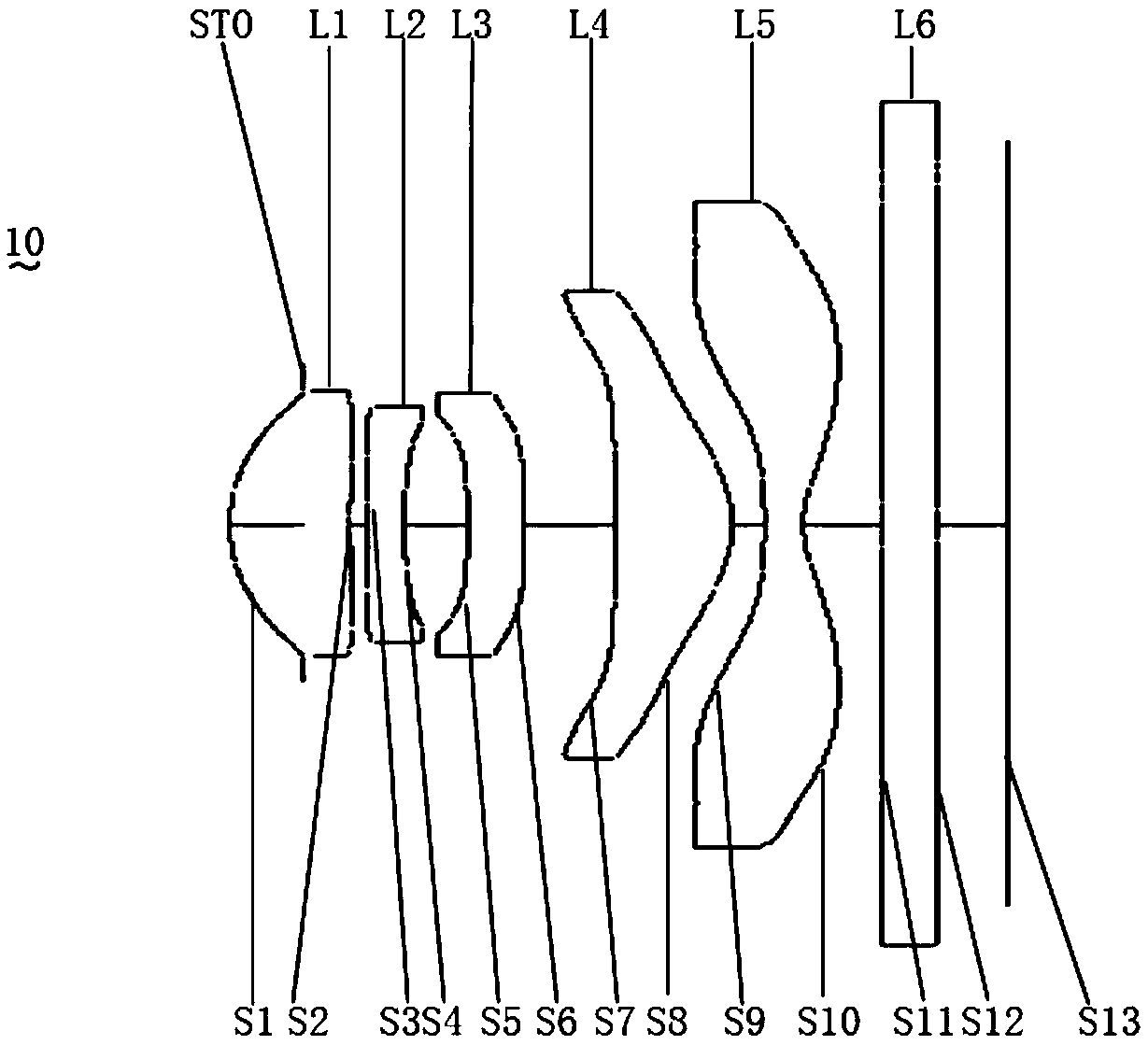
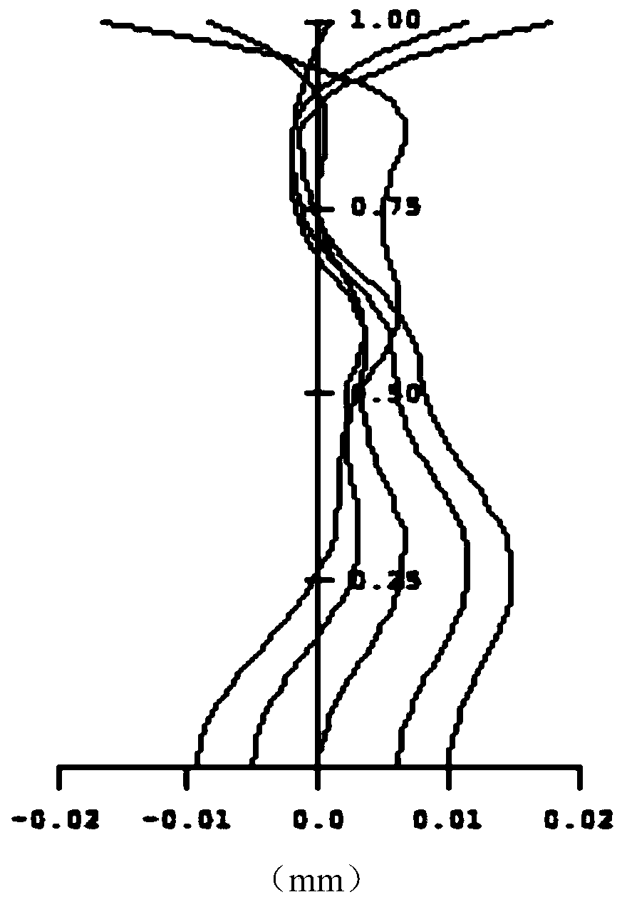
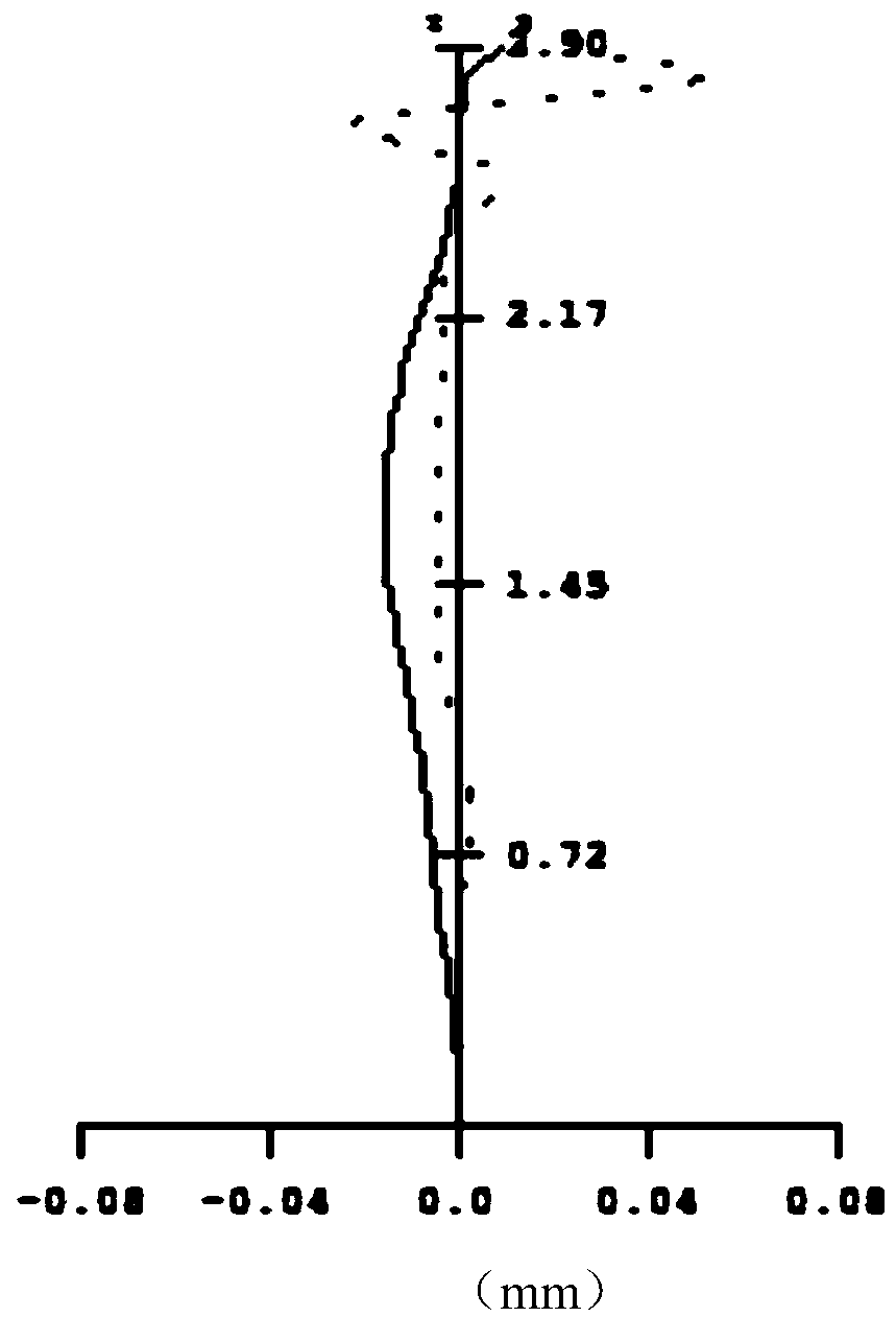
[0075] see Figure 1 to Figure 4 , from the object side to the image side, the imaging lens 10 of the first embodiment includes an aperture STO, a first lens L1, a second lens L2, a third lens L3, a fourth lens L4, a fifth lens L5 and an infrared filter Slice L6.

[0076] The first lens L1 has positive refractive power and is made of plastic. The object side S1 is convex, and the image side S2 is concave at the optical axis and convex at the circumference, both of which are aspherical. The second lens L2 has a negative refractive power and is made of plastic. The object side S3 is convex, and the image side S4 is concave, both of which are aspherical. The third lens L3 has negative refractive power and is made of plastic. The object side S5 is concave, and the image side S6 is convex, both of which are aspherical. The fourth lens L4 has positive refractive power and is made of plastic. The object side S7 is convex at the optical axis and concave at the circumference, and the...

no. 2 example

[0086] see Figure 5 to Figure 8 , from the object side to the image side, the imaging lens 10 of the first embodiment includes an aperture STO, a first lens L1, a second lens L2, a third lens L3, a fourth lens L4, a fifth lens L5 and an infrared filter Slice L6.

[0087] The first lens L1 has positive refractive power and is made of plastic. The object side S1 is convex, and the image side S2 is concave at the optical axis and convex at the circumference, both of which are aspherical. The second lens L2 has negative refractive power and is made of plastic. The object side S3 is concave at the optical axis and convex at the circumference, and the image side S4 is concave and aspherical. The third lens L3 has negative refractive power and is made of plastic. The object side S5 is concave, and the image side S6 is concave at the optical axis and convex at the circumference, both of which are aspherical. The fourth lens L4 has positive refractive power and is made of plastic. T...

no. 3 example

[0099] see Figure 9 to Figure 12 , from the object side to the image side, the imaging lens 10 of the first embodiment includes an aperture STO, a first lens L1, a second lens L2, a third lens L3, a fourth lens L4, a fifth lens L5 and an infrared filter Slice L6.

[0100] The first lens L1 has positive refractive power and is made of plastic. The object side S1 is convex, and the image side S2 is concave at the optical axis and convex at the circumference, both of which are aspherical. The second lens L2 has a negative refractive power and is made of plastic. The object side S3 is convex, and the image side S4 is concave, both of which are aspherical. The third lens L3 has a negative refractive power and is made of plastic. The object side S5 is convex at the optical axis and concave at the circumference, and the image side S6 is concave at the optical axis and convex at the circumference. Aspherical. The fourth lens L4 has positive refractive power and is made of plastic....


PUM


Abstract

The invention discloses an image pick-up camera, an image capture device and an electronic device. The image pick-up camera comprises a diaphragm, a first lens with positive refractive power, a secondlens with negative refractive power, a third lens with negative refractive power, a fourth lens with positive refractive power and a fifth lens with negative refractive power which are sequentially distributed from an object side to an image side; the image side surface of the first lens is a concave surface at the optical axis of the camera and a convex surface at the circumference of the camera; the image side surface of the fourth lens is a convex surface at the optical axis; the image side surface of the fifth lens is a concave surface at the optical axis; and at least one of the object side surface and image side surface of the fifth lens has at least one inflection point. The image pick-up camera satisfies the relational expression that 1<R4/f<1.5, wherein R4 is the curvature radiusof the image side surface of the second lens, and f is the effective focal length of the image pick-up camera. The image pick-up camera has reasonable lens configuration and meets the relational expression 1 that 1<R4/f< 1.5, and therefore, aberration can be avoided, high-order aberration generated by the second lens can be corrected, and imaging quality is improved.

Description

technical field [0001] The invention relates to optical imaging technology, in particular to a camera lens, an image taking device and an electronic device. Background technique [0002] Traditionally, optical systems mounted on electronic products mainly use four-piece lens structures. However, due to the prevalence of high-standard electronic devices such as Smart Phones and Tablet PCs, the optical system has become more advanced in terms of pixels and imaging quality. With the rapid rise of the technology, the known optical system will not be able to meet the higher-order photography system. Therefore, there is an urgent need for a photographic optical system with better imaging quality. Contents of the invention [0003] Embodiments of the present invention provide a camera lens, an image capturing device, and an electronic device. [0004] The imaging lens according to the embodiment of the present invention includes a diaphragm, a first lens with positive refractiv...

Claims


Application Information

Patent Timeline
Patent Type & Authority Applications(China)
IPC IPC(8): G02B13/00G02B13/18
CPCG02B13/0045G02B13/18
Inventor 邹海荣刘彬彬邹金华兰宾利
Owner JIANGXI JINGCHAO OPTICAL CO LTD
Why Eureka
Try Eureka