Emergency escape equipment for rail transit vehicle

A technology for rail transit and traffic vehicles, which is applied in the field of emergency escape equipment for rail transit vehicles. It can solve problems such as rope wear, narrow application range, and decreased safety factor, and achieve the effects of convenient recycling, wide application range, and low friction

Pending Publication Date: 2020-03-06
湖北善流电子科技有限公司
View PDF0 Cites 0 Cited by
  • Summary
  • Abstract
  • Description
  • Claims
  • Application Information

AI Technical Summary

Problems solved by technology

[0003] Due to the high altitude of rail transit vehicles, it is generally necessary to use high-altitude escape equipment. The existing high-altitude escape equipment generally uses a motor to drive the rope roll to rotate, so that the rope is lowered, and a hanging basket is fixed at one end of the rope, and the passenger is rescued by the hanging basket. However, due to the lack of power of the rail transit vehicle during an emergency stop, the motor will not be able to run. This kind of high-altitude escape equipment cannot be used, and it cannot escape. The scope of application is narrow, and the rope will be damaged when the hanging basket Friction with the lower edge of the window will cause the rope to be worn, the safety factor will decrease, and when the hanging basket descends, it will scrape on the outer wall of the rail transit vehicle, causing damage to the rail transit vehicle and increasing maintenance costs

Method used


Image

  • Emergency escape equipment for rail transit vehicle
  • Emergency escape equipment for rail transit vehicle
  • Emergency escape equipment for rail transit vehicle

Examples


Embodiment Construction

[0026] The following will clearly and completely describe the technical solutions in the embodiments of the present invention with reference to the accompanying drawings in the embodiments of the present invention. Obviously, the described embodiments are only some, not all, embodiments of the present invention.

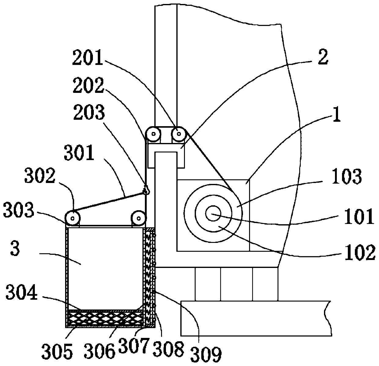
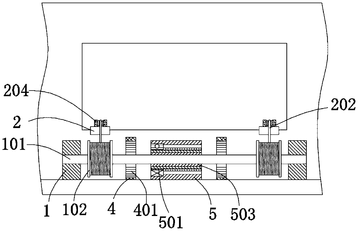
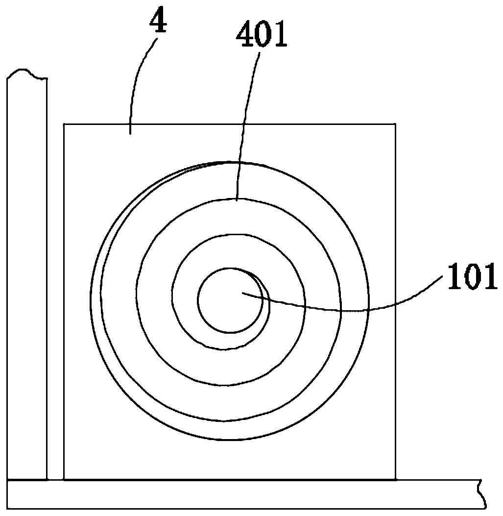
[0027] refer to Figure 1-7 , an emergency escape device for a rail transit vehicle, comprising a hanging basket 3, two clamping blocks 2 and two first support seats 1, the inner walls of the two first support seats 1 are connected with the same rotating shaft 101 through bearings, and the first The support base 1 is welded to the inner bottom of the rail transit car, and both sides of the outer wall of the rotating shaft 101 are sleeved with rope winding rollers 102, and the outer wall of the rope winding roller 102 is sleeved with a rope roll 103, and the rope output end of the rope roll 103 is pulled out There is a rope 202, the outer wall of the rotating shaft 10...


PUM


Abstract

The invention belongs to the technical field of rail transit, and particularly relates to emergency escape equipment for a rail transit vehicle. Aiming at the technical problems of narrow range, ropeabrasion and damage to the outer wall of the vehicle, the emergency escape equipment comprises a hanging basket, two clamping blocks and two first supporting seats, wherein the inner walls of the twofirst supporting seats are provided with the same rotating shaft, the first supporting seats are arranged at the inner bottom of a rail transit carriage, the two sides of the outer wall of the rotating shaft are respectively provided with a rope winding roller, the outer walls of the rope winding rollers are provided with rope coils, a rope is pulled out of the rope outlet end of each rope coil, the outer wall of the rotating shaft is provided with a groove with a fan-shaped cross section, the outer wall of the rotating shaft is provided with a gear sleeve, a stop block is welded to the innerwall of the gear sleeve, and the inner wall of the gear sleeve is provided with a pressing groove. According to the emergency escape equipment for the rail transit vehicle, passengers can escape on the ground by self gravity without depending on electric power, the application range is wide, the escape safety of the passengers is improved, and the collision of the hanging basket is prevented fromdamaging the side wall of the carriage.

Description

technical field [0001] The invention relates to the technical field of rail transit, in particular to an emergency escape device for a rail transit vehicle. Background technique [0002] The rail transit vehicles in Chongqing generally run on the monorail at a height of about 20 meters from the ground. When the rail transit vehicle encounters an unexpected emergency stop on the monorail, it is necessary to evacuate the passengers in the vehicle to prevent accidents. Because the width of the rail transit car is greater than the width of the monorail, there is no free space on both sides of the rail transit car for passengers to get off and avoid danger, so it is necessary to use an escape device for emergency escape. [0003] Due to the high altitude of rail transit vehicles, it is generally necessary to use high-altitude escape equipment. The existing high-altitude escape equipment generally uses a motor to drive the rope roll to rotate, so that the rope is lowered, and a ha...

Claims


Application Information

Patent Timeline
IPC IPC(8): B61B12/00
CPCB61B12/005
Inventor 不公告发明人
Owner 湖北善流电子科技有限公司
Why Eureka
Try Eureka