
Nozzle fastening system for open-end rotor spinning device

A rotor spinning, free end technology, applied in the directions of free end spinning machine, spinning machine, continuous winding spinning machine, etc., can solve the problems of blocking fixed locking, blockage, influence, etc., and achieve the effect of a simple way

Active Publication Date: 2020-03-06
SAURER SPINNING SOLUTIONS GMBH & CO KG
View PDF15 Cites 0 Cited by
  • Summary
  • Abstract
  • Description
  • Claims
  • Application Information

AI Technical Summary

Problems solved by technology

Another disadvantage is that the outwardly exposed recesses can become clogged with fibers and dirt, as a result, affecting or hindering the fixed locking

Method used


Image

  • Nozzle fastening system for open-end rotor spinning device
  • Nozzle fastening system for open-end rotor spinning device
  • Nozzle fastening system for open-end rotor spinning device

Examples


Embodiment Construction

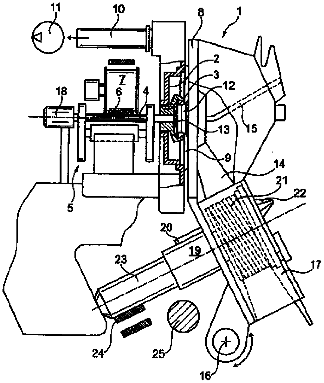
[0074] figure 1 An open-end rotor spinning device 1 is shown schematically. As is known, such open-end rotor spinning devices 1 each have a rotor housing 2 in which the spinning cup of the spinning rotor 3 rotates at a high rotational speed.

[0075] The spinning rotor 3 is supported, for example with its rotor shaft 4 , in a wedge-shaped support gap of a so-called support disc bearing system 5 , the spinning rotor 3 is frictionally driven by a tangential belt 6 which extends the length of the machine and is driven by Press roller 7 is actuated.

[0076] For example, the rotor shaft 4 is fixed axially by means of a permanent magnetic thrust bearing 18 .

[0077] The rotor housing 2 which itself opens forward is closed during the spinning operation by a pivotally mounted cover element 8 into which a channel plate is provided which rests against the rotor by means of a circumferentially extending intermediate seal 9 Housing 2 is placed.

[0078] The rotor housing 2 is also c...


PUM

PropertyMeasurementUnit
angleaaaaaaaaaa

Abstract

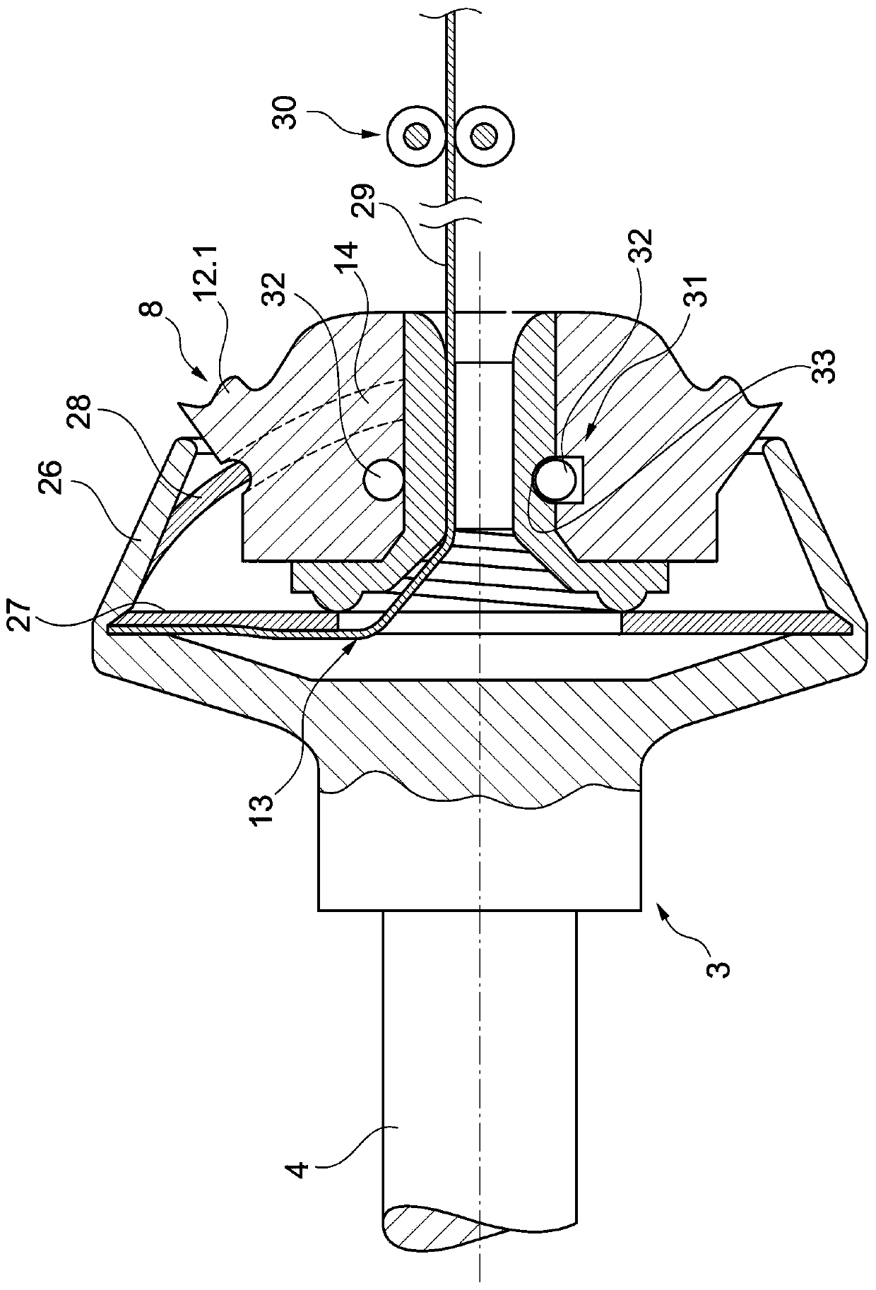
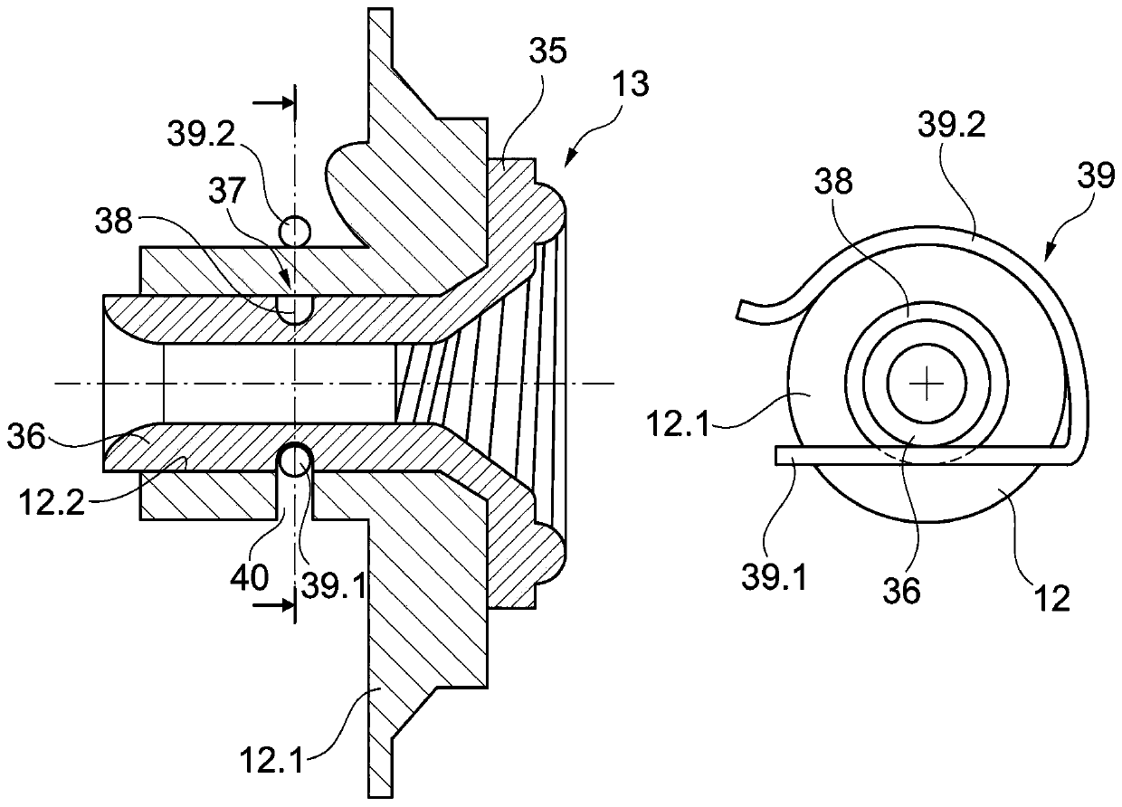
The invention relates to a nozzle fastening system for an open-end rotor spinning device (1) for replaceably fastening a thread-drawing nozzle (13) to a holder (12) arranged in a cover element (8). The nozzle fastening system includes: a clamp fastener (31) for axially fixing the wire-drawing nozzle (13); at least one clamping member (32) and a matching member (33), which are distributed in the The thread-drawing nozzle (13) and the holder (12). The clamping member (32) is elastic in the radial direction. A groove (37) is provided on the nozzle shaft (36) of the thread-drawing nozzle (13) to serve as a fitting (33). The clamping member (32) is composed of a spring wire (39). The spring wire (39) has a straight portion (39.1). In the fixed state, the straight portion (39.1) of the spring wire (39) is locked into the groove (37) on the nozzle shaft (36) and is tangential to the nozzle shaft (36).

Description

technical field [0001] The invention relates to a nozzle fastening system for an open-end rotor spinning device for replaceably fastening a thread-drawing nozzle to a holder in a cover element, the nozzle fastening system comprising: The thread-drawing nozzle is fixed in the axial direction; at least one clamping part and a matching part are distributed among the thread-drawing nozzle and the holding part; the clamping part is elastic in the radial direction. Background technique [0002] For example, the thread withdrawal nozzle can be fastened replaceably to a channel plate adapter of a so-called cover element which closes the open-end rotor spinning device during the spinning operation. Since the thread-drawing nozzle is exposed to severe wear due to the advancing yarn, the thread-drawing nozzle typically has a funnel-shaped nozzle insert made of a highly wear-resistant material, preferably technical ceramics, and bonded, for example by means of an adhesive Or the press ...

Claims


Application Information

Patent Timeline
Patent Type & Authority Applications(China)
IPC IPC(8): D01H4/40
CPCD01H4/40
Inventor L·温岑
Owner SAURER SPINNING SOLUTIONS GMBH & CO KG
Learn More