
Drive motor and bead grinding machine disc lifting mechanism

A technology for driving motors and lifting mechanisms, applied in the direction of grinding drive devices, electromechanical devices, electrical components, etc., can solve problems such as poor working stability, waste of space resources, and increased costs, and achieve easy installation and disassembly, and firm axial fixation , the effect of improving work efficiency

Inactive Publication Date: 2016-02-10
浦江县合芯电子科技有限公司
View PDF6 Cites 0 Cited by
  • Summary
  • Abstract
  • Description
  • Claims
  • Application Information

AI Technical Summary

Problems solved by technology

It generally includes a casing, a stator, a rotor and a rotating shaft. The rotating shaft can output power to drive the power machinery to work. At present, the rotating shafts of existing motors are generally solid structures, and the motors of this structure can be applied to power machinery in various fields. However, the motor has at least the following defects: the solid structure of the shaft has a high cost, and the power machinery (including bead grinding machines, etc.) connected to it can only be connected to its end, resulting in a waste of space resources , that is to say, after it is connected with the power machinery, the volume of the whole machine is relatively large
In addition, crystal is a colorless and transparent large-scale quartz crystal mineral, which generally needs to be polished on the surface. The grinding methods include various processing methods including manual grinding and bead grinding machine grinding. Manual grinding will inevitably result in defective products. The efficiency is high, the cost is high, and the technical level of the workers is too high, which is not suitable for large-scale industrial production; while the existing bead grinding machines generally include a frame with a grinding disc on the frame, and the grinding disc is connected to the lifting mechanism. , the advantage of this solution is that the grinding disc can be lifted and lowered automatically, which virtually reduces the operator's work intensity. In addition, the bead grinding machine with this structure not only replaces manual operation, but also further improves production efficiency and reduces production costs. Cost, etc., but this bead grinding machine also has at least the following defects: the volume of the whole machine is large and the structure is not compact, that is to say, the space area required for its installation is relatively large, which causes a certain waste of existing space resources; In addition, the manufacturing cost of the existing bead grinding machine is relatively high, which does not conform to the current trend of social technology development
[0004] The above two solutions have improved some problems of the prior art to a certain extent, however, the rotating shafts of the main motor and the vertical stepping motor of the first solution are solid structures, and the rotating shafts of the translational motors of the second solution are also solid structures , its cost is relatively high, and both of these two solutions have at least the following defects. The structure of the whole machine is complex and not compact, that is to say, the volume of the whole machine is relatively large, which virtually increases the cost of production and manufacturing. In addition, the work is stable sex is also poor

Method used


Image

  • Drive motor and bead grinding machine disc lifting mechanism
  • Drive motor and bead grinding machine disc lifting mechanism
  • Drive motor and bead grinding machine disc lifting mechanism

Examples


Embodiment 1

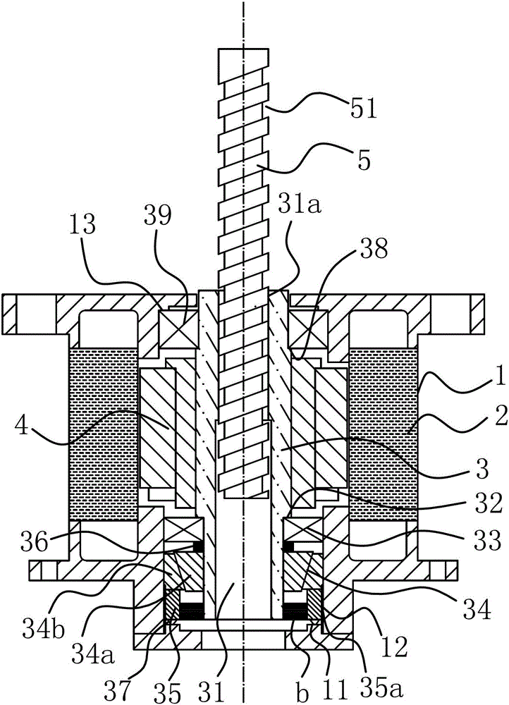
[0028] like figure 1 As shown, the driving motor includes a housing 1, a stator 2 and a rotor shaft 3 pierced in the stator 2 are arranged in the housing 1, and a rotor 4 is fixed on the rotor shaft 3, and the rotor shaft 3 and the housing The body 1 is axially positioned and connected in a circumferential direction. An axially positioned rolling structure is provided between the rotor shaft 3 and the housing 1. A channel 31 for the drive rod 5 to enter is provided at the axial center of the rotor shaft 3. The channel 31 is provided with a connection structure that can be connected with the driving rod 5 and can drive the driving rod 5 to move axially in the channel 31 when the rotor shaft 3 rotates. Obviously, the design of the drive motor in this embodiment is more reasonable, can greatly save space, makes the overall structure compact, and the relative connection method is very simple, easy to install and disassemble, virtually improves work efficiency, and conforms to the ...

Embodiment 2

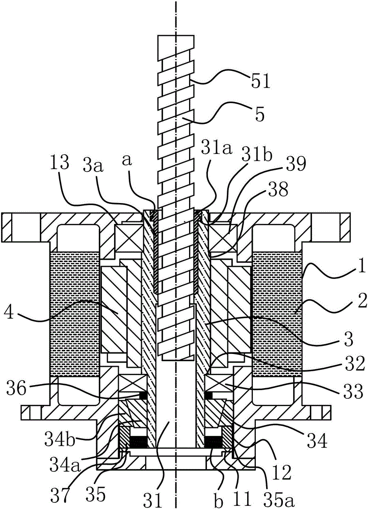
[0035] like figure 2 , 4 As shown, the structure and principle of this embodiment are basically the same as that of Embodiment 1, the difference is that the connection structure includes a screw sleeve 3a fixed in the passage 31 and having an internal thread 31a and a screw sleeve 3a arranged on the drive rod 5 The external thread 51, the internal thread 31a is threadedly connected with the external thread 51, the optimization scheme, the outer side of the screw sleeve 3a here is provided with an annular shoulder a, and an annular step 31b is provided at the end of the passage 31, and the screw sleeve The inner end of 3a is inserted into the channel 31 and the annular shoulder a is fixed on the annular step 31b.

Embodiment 3

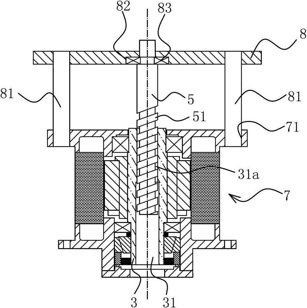
[0037] like Figure 5 As shown, the structure and principle of the present embodiment are basically the same as those of the first embodiment, except that one end of the channel 31 is closed.


PUM


Abstract

The invention belongs to the technical field of bead mills, and particularly relates to a driving motor and a milling disc lifting mechanism of a bead mill, which solve the technical problems of unreasonable design and the like of the prior art. The driving motor comprises a casing, wherein a stator and a rotor shaft are arranged in the casing, the rotor shaft is arranged in the stator in a penetrating way, a rotor is fixedly arranged on the rotor shaft, the rotor shaft and the casing are axially positioned and are circumferentially and rotatably connected, the axial center of the rotor shaft is provided with a passage, a driving rod can enter the passage, and a connecting structure is arranged between the passage and the driving rod and is used for driving the driving rod to axially move in the passage when the rotor shaft rotates. The milling disc lifting mechanism of the bead mill comprises the driving motor and a lifting plate, wherein the axial center of the rotor shaft of the driving motor is provided with the passage, and the driving rod can enter the passage. Compared with the prior art, the driving motor and the milling disc lifting mechanism have the advantages that the cost is low, the installation and the connection are convenient, the integral size is small, the structure is simple and compact, the installation space is reduced, and the trend of the current social technology development is met.

Description

technical field [0001] The invention belongs to the technical field of bead grinding machines, and in particular relates to a driving motor and a lifting mechanism for a grinding disc of a bead grinding machine. Background technique [0002] As a general power machine, the motor is widely used in various fields. It generally includes a casing, a stator, a rotor and a rotating shaft. The rotating shaft can output power to drive the power machinery to work. At present, the rotating shafts of existing motors are generally solid structures, and the motors of this structure can be applied to power machinery in various fields. However, the motor has at least the following defects: the solid structure of the shaft has a high cost, and the power machinery (including bead grinding machines, etc.) connected to it can only be connected to its end, resulting in a waste of space resources , That is to say, after it is connected with the power machinery, the volume of the whole machine i...

Claims


Application Information

Patent Timeline
Patent Type & Authority Patents(China)
IPC IPC(8): H02K7/14B24B47/00F16H25/20
Inventor 方铝清颜东红
Owner 浦江县合芯电子科技有限公司
Learn More