
An Efficient Dyeing and Finishing Cloth Dehydration Device

A dehydration device and cloth technology, applied in the direction of instruments, liquid/gas/steam removal by centrifugal force, alarm, etc., can solve problems such as corrosion, achieve high stability, good early warning effect, and convenient loading and unloading maintenance

Active Publication Date: 2021-12-17
FUJIAN HANGGANG TEXTILE TECH CO LTD
View PDF13 Cites 0 Cited by
  • Summary
  • Abstract
  • Description
  • Claims
  • Application Information

AI Technical Summary

Problems solved by technology

[0005] However, the dehydration equipment in this utility model patent has the problem that the motor is located under the drum and may be corroded by water

Method used


Image

  • An Efficient Dyeing and Finishing Cloth Dehydration Device
  • An Efficient Dyeing and Finishing Cloth Dehydration Device
  • An Efficient Dyeing and Finishing Cloth Dehydration Device

Examples


Embodiment Construction

[0022] The following descriptions are only preferred embodiments of the present invention, and do not limit the scope of the present invention.

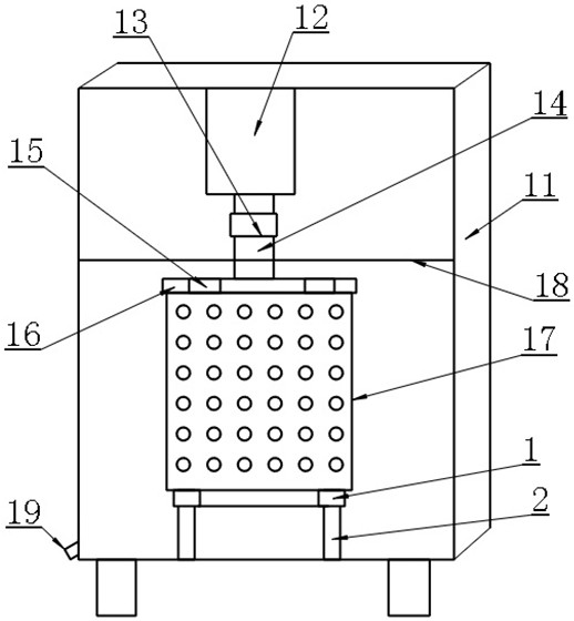
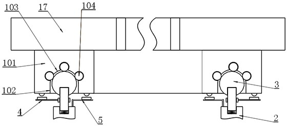
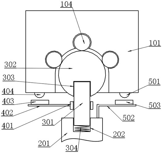
[0023] Example: as attached figure 1 , 2 , 3 and attached Figure 4 As shown, a kind of efficient dyeing and finishing fabric dehydration device includes a casing 11 for receiving water, and also includes a driving motor 12 arranged on the inner top surface of the casing 11, and the driving motor 12 is arranged on the The coupling 13 on the shaft, the rotating shaft 14 arranged on the coupling 13, the upper end plate 16 of the drum which is arranged on the rotating shaft 14 and provided with the cloth inlet and outlet 15, is arranged on the upper end plate of the drum 16 the dehydration drum main body 17 on the lower surface, the ring groove unit 1 arranged on the lower surface of the dehydration drum main body 17, the support column unit 2 arranged on the inner bottom surface of the casing 11, the support column unit 2 arranged on...


PUM


Abstract

The invention belongs to the technical field of dehydration equipment structure, and in particular relates to an efficient dehydration device for dyeing and finishing fabrics. In the present invention, a drive motor is arranged above the casing, and a ring groove unit, a support column unit, an installation ring unit, an inclination warning unit and an overweight warning unit are arranged on the lower surface of the main body of the dehydration drum to achieve efficient and safe dehydration. Effect. The invention has the advantages of reasonable and effective dehydration structure, the motor is not easy to be corroded by water immersion, the early warning effect is good when the drum is overweight or tilted, the early warning structure is simple and flexible, does not affect the normal dehydration operation, and the overall structure of the dehydration device has high stability and is convenient for loading, unloading and maintenance.

Description

technical field [0001] The invention belongs to the technical field of dehydration equipment structure, and in particular relates to an efficient dehydration device for dyeing and finishing fabrics. Background technique [0002] In the process of fabric dyeing and finishing, a dehydration device is needed. The existing dehydration device is mainly composed of an upper roller and a lower motor structure. This structure has the problem that the removed water easily wets the motor, causing the motor to rust and corrode. [0003] And on the other hand, the existing simple drum structure is prone to the problem of drum tilting after adding uneven weight and asymmetric cloth, that is, when a large amount of cloth is accumulated in one part of the drum and less cloth in another place, the motor drives During the process, there will be a large shake, which will eventually damage the motor and the motor shaft structure. Therefore, there is an urgent need in the market for a new type ...

Claims


Application Information

Patent Timeline
Patent Type & Authority Patents(China)
IPC IPC(8): D06B15/10G08B21/18
CPCD06B15/10G08B21/18
Inventor 祝学政汪培张桂萍吴建波
Owner FUJIAN HANGGANG TEXTILE TECH CO LTD
Learn More