
Oil tank dewatering device

A technology of dehydration device and oil tank, which is applied in the direction of liquid separation, chemical instruments and methods, separation methods, etc., and can solve problems such as dehydration

Inactive Publication Date: 2008-08-06
赵晓晔
View PDF0 Cites 3 Cited by
  • Summary
  • Abstract
  • Description
  • Claims
  • Application Information

AI Technical Summary

Problems solved by technology

The dehydration device solves the technical problem of removing water from the oil by judging the weighing value of the body

Method used


Image

  • Oil tank dewatering device

Examples


Embodiment Construction

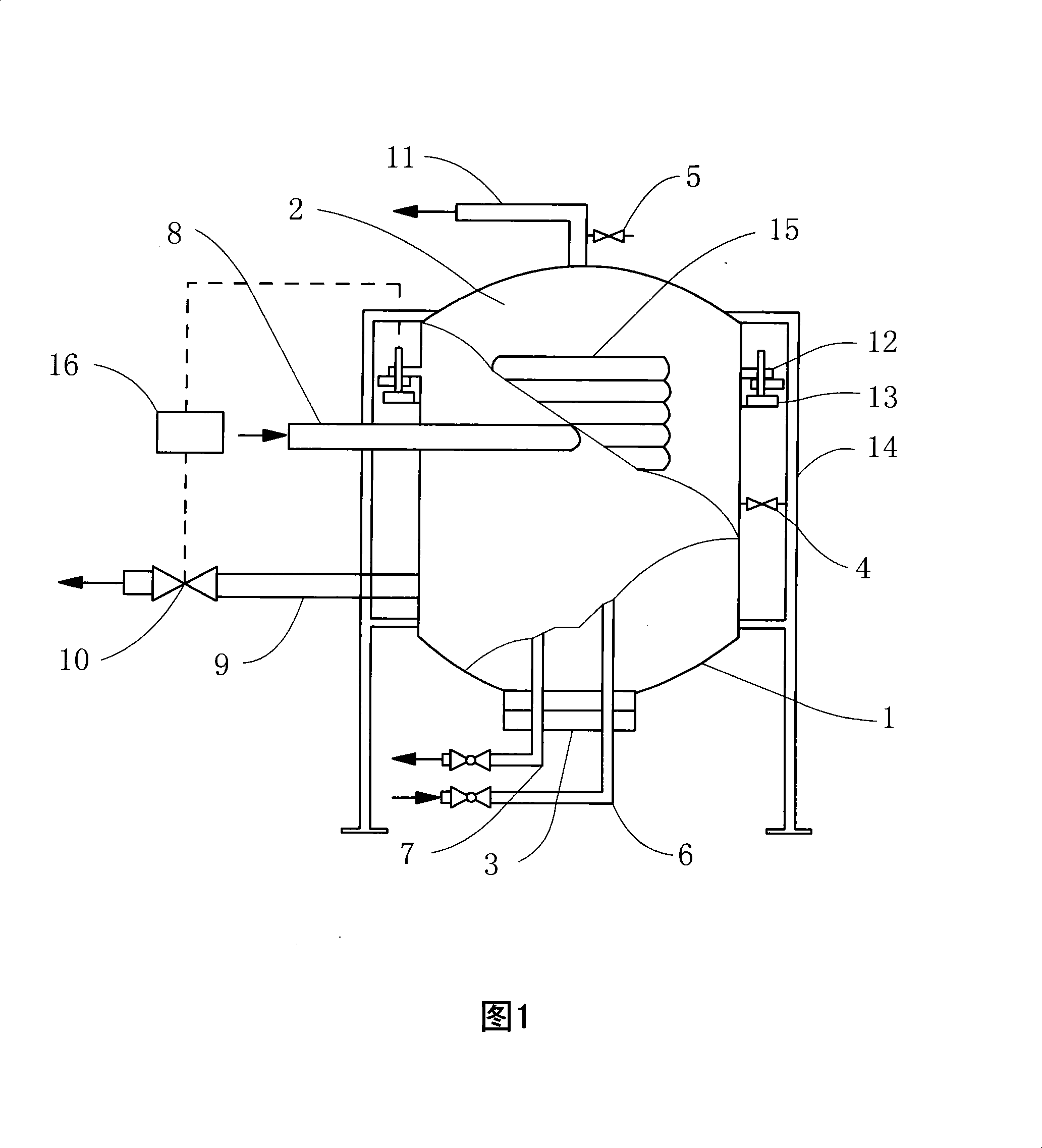
[0008] As shown in Figure 1, a chamber 2 is provided in the dehydrator body 1, and heat exchange tubes 15 are arranged spirally in the dehydrator chamber, the two ends of which are connected with the steam inlet pipe 6 and the steam outlet pipe 7 respectively. The bottom is provided with a sewage outlet 3, the upper part is provided with an oil phase connecting pipe 11, the water inlet pipe 4 is connected to the lower side of the dehydrator, and the water outlet pipe 5 is connected to the upper side or the oil phase connecting pipe, and the lower part of the other side of the dehydrator A drain pipe 9 is connected, on which a drain valve 10 is installed, and an oil-water inlet pipe 8 is connected at a tangent angle in the middle of the dehydrator, and a weighing support ring 12 is provided in the upper middle of the dehydrator, and a weighing sensor 13 is in contact with the support ring Connect, be connected with weight acquisition controller 16 by wire between drain valve and...


PUM


Abstract

The invention provides an oil tank dehydrating device, which belongs to the field of petroleum and chemical engineering, a cavity is arranged inside a dehydrator, inside the dehydrator is provided with a heat exchanger tube which is communicated with the inlet and outlet pipes of steam, the bottom of the dehydrator is provided with a sewage discharge outlet, the upper part is provided with oil-phase connecting pipe, the dehydrator is connected with a water inlet and outlet pipe, the other side of the dehydrator is in connection with an offlet and a drain valve, the central tangential angle of the dehydrator is in connection with an inlet pipe for oil and water, the upper middle part of the dehydrator is provided with a weighing supporting ring which is in contact connection with a weighing sensor, a weight collecting controller is connected between the drain valve and the weighing sensor through conductors. The device of the invention is characterized in that first, the weighing process is accurate, the working condition is stable and reliable; second, the dehydrator can carry out the process of twice-separation of oil and water; third, weight collecting controller can be used for controlling and displaying dehydrating process, and the device is suitable for oil dehydrating in petroleum processing.

Description

technical field [0001] The invention provides an oil tank dehydration device for removing water from oil product tanks in the field of petrochemical industry. Background technique [0002] After the oil containing water in the oil tank enters the tank, it undergoes static oil-water separation, and the water contained in it will gradually sink to the bottom of the tank, or the water in the tank will come out from time to time. Before the present invention was proposed, the lower part of the oil storage tank was connected with a water discharge valve. After the oil product stayed in the tank for a period of time, the water sank to the bottom of the tank. The water discharge valve was manually opened to observe whether the discharged water contained oil by human eyes. There may be an emulsified transition layer, which is difficult to judge by human eyes. Therefore, when the water in the tank is discharged, the oil product is easily discharged, which will not only cause oil leak...

Claims


Application Information

Patent Timeline
IPC IPC(8): B01D17/032
Inventor 赵晓晔张宇翔
Owner 赵晓晔
Learn More