A kind of inner surface milling processing equipment

A technology of milling and inner surface, which is applied in metal processing equipment, milling machine equipment, details of milling machine equipment, etc., can solve problems such as low efficiency, low machining accuracy, and inability to process thread grooves, etc., to achieve reduced vibration, high machining accuracy, Good milling effect

Active Publication Date: 2020-09-04
昆山市拓川诚自动化设备有限公司
View PDF8 Cites 0 Cited by
  • Summary
  • Abstract
  • Description
  • Claims
  • Application Information

AI Technical Summary

Problems solved by technology

[0003] However, for the inner surface of the set workpiece, due to the structural limitations of the existing milling machine, it cannot be processed well. For example, the inner surface of the metal sleeve needs to be processed with a groove of a certain shape. Currently, the metal is usually processed in the form of a planer. The inner surface of the casing, but this processing method not only has low efficiency and low processing accuracy, but also cannot process threaded grooves

Method used


Image

  • A kind of inner surface milling processing equipment
  • A kind of inner surface milling processing equipment
  • A kind of inner surface milling processing equipment

Examples


Embodiment Construction

[0020] All features disclosed in this specification, or steps in all methods or processes disclosed, may be combined in any manner, except for mutually exclusive features and / or steps.

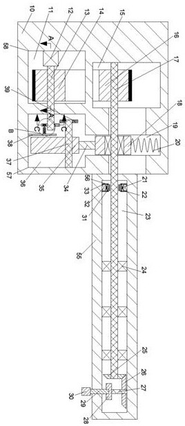
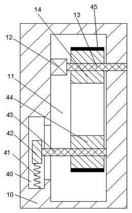
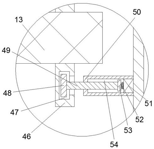
[0021] Combine below Figure 1-5 The present invention is described in detail, and for convenience of description, the orientations mentioned below are now stipulated as follows: figure 1 The up, down, left, right, front and back directions of the projection relationship itself are the same.

[0022] Such as Figure 1-5 As shown, a mechanical structure diagram of an inner surface milling processing equipment of the device of the present invention mainly includes a casing 10, the right end of the casing 10 is provided with a rotating column 55 that can extend into the inside of the workpiece, and the rotating column 55 is equipped with a There is a rotating chamber 23, the upper and lower end walls of the rotating chamber 23 are provided with two symmetrical rotating mechanisms 56, and the ro...


PUM


Abstract

The invention provides inside surface milling equipment. The equipment mainly comprises a casing, and the right end of the casing is provided with a rotating column which can extend into a processingpiece; the rotating column is internally provided with a rotating cavity, and the upper and lower end walls of the rotating cavity are provided with two symmetrical rotating mechanism; each rotating mechanism comprises an abutting block, and the rotting cavity is internally provided with a transmission shaft; the abutting blocks can be tightly attached to the transmission shaft, and rotated with the transmission shaft; the transmission shaft is driven to rotate for achieving rotation of a milling part, and the rotating cavity is internally provided with a fixing base which can be used for fixing a milling cutter; the transmission shaft is rotated for driving the milling cutter to rotate for milling, and the casing is internally provided with a movable block connected with the transmissionshaft rotatably; the lower side of the movable block is provided with a moving mechanism which can be used for moving the movable block, and horizontal movement of the milling part is achieved; and the casing is internally provided with a driving mechanism used for providing power for rotation of the transmission shaft and movement of the moving mechanism. According to the inside surface milling equipment, the inside surface of the processing piece can be milled, and the milling cutter can be used for milling the processing piece under the control of a computer numerical control milling machine in any direction.

Description

technical field [0001] The invention relates to the technical field of milling, in particular to an inner surface milling processing equipment. Background technique [0002] A milling machine is a machine tool with a wide range of uses. It can process planes (horizontal planes, vertical planes), grooves (key slots, T-shaped slots, dovetail slots, etc.), toothed parts (gears, spline shafts, sprockets), Spiral surface (thread, spiral groove) and various curved surfaces. In addition, it can also be used to process the surface and inner hole of the rotating body and perform cutting work. [0003] However, for the inner surface of the set workpiece, due to the structural limitations of the existing milling machine, it cannot be processed well. For example, the inner surface of the metal sleeve needs to be processed with a groove of a certain shape. Currently, the metal is usually processed in the form of a planer. The inner surface of the casing, but this processing method not ...

Claims


Application Information

Patent Timeline
Patent Type & Authority Patents(China)
IPC IPC(8): B23C3/00B23Q3/00B23Q5/34B23Q11/00
CPCB23C3/00B23Q3/00B23Q5/34B23Q11/0032
Inventor 袁宗周
Owner 昆山市拓川诚自动化设备有限公司
Why Eureka
Try Eureka