Motor rotor, motor and electric vehicle

A technology for motor rotors and electric vehicles, applied in electric vehicles, motors, electric components, etc., can solve the problems of less amount of magnetic steel, affecting the service life of motors, and excessive stress concentration.

Active Publication Date: 2020-03-10
BYD CO LTD
View PDF9 Cites 6 Cited by
  • Summary
  • Abstract
  • Description
  • Claims
  • Application Information

AI Technical Summary

Problems solved by technology

[0002] Motors are widely used as driving devices in various technical fields. For example, they can be used as the driving motor of electric vehicles to realize the function of driving vehicles. However, due to the limitation of layout space, it is usually necessary to design a small-volume drive motor, and the small-volume drive motor uses too little magnetic steel due to the limited layout space, which reduces the air gap flux density and electromagnetic torque.
In th

Method used


Image

  • Motor rotor, motor and electric vehicle
  • Motor rotor, motor and electric vehicle
  • Motor rotor, motor and electric vehicle

Examples


Embodiment Construction

[0033] Specific embodiments of the present disclosure will be described in detail below in conjunction with the accompanying drawings. It should be understood that the specific embodiments described here are only used to illustrate and explain the present disclosure, and are not intended to limit the present disclosure.

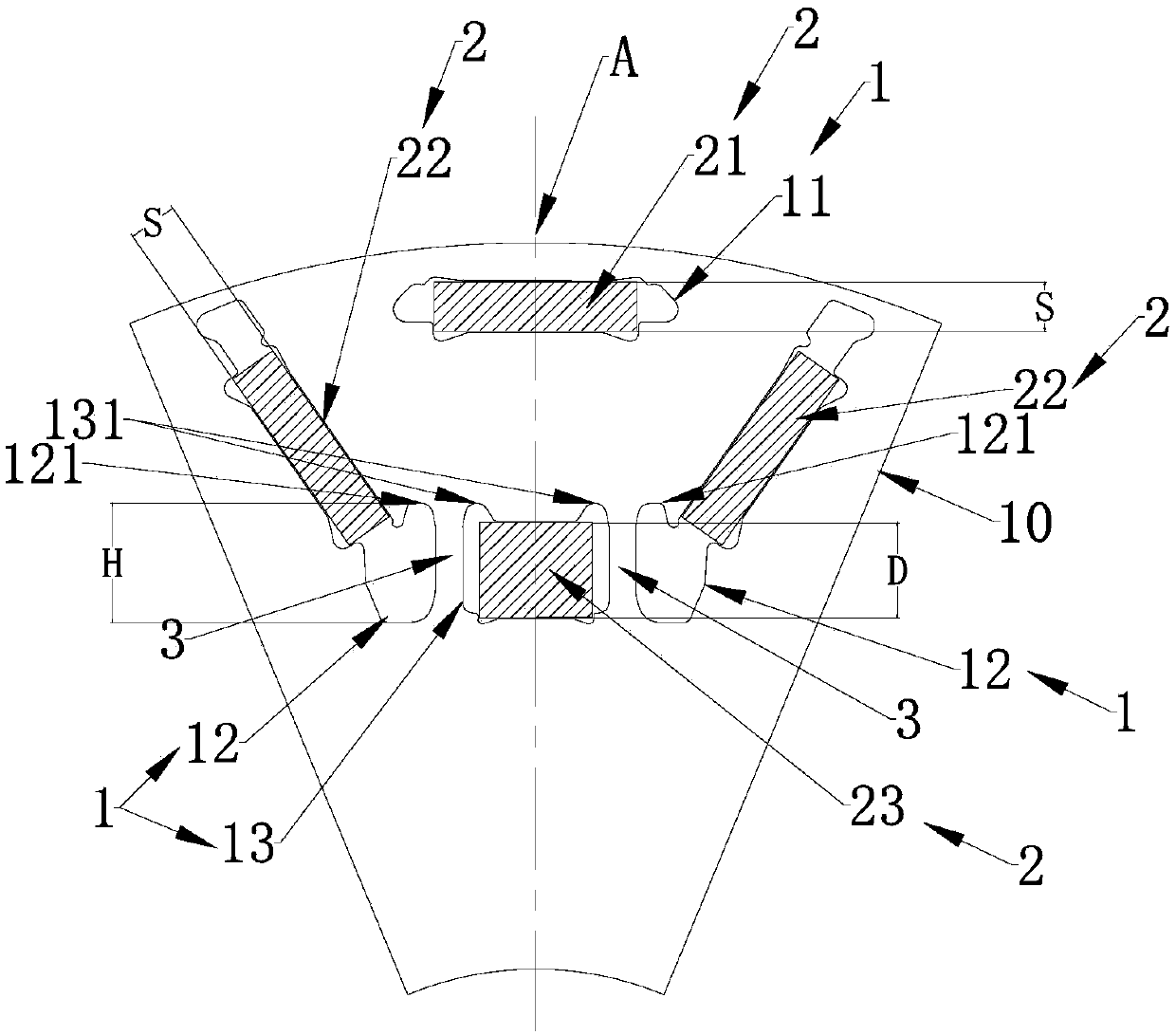
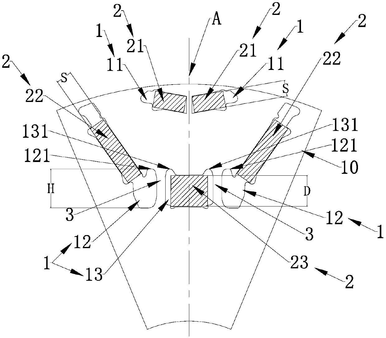
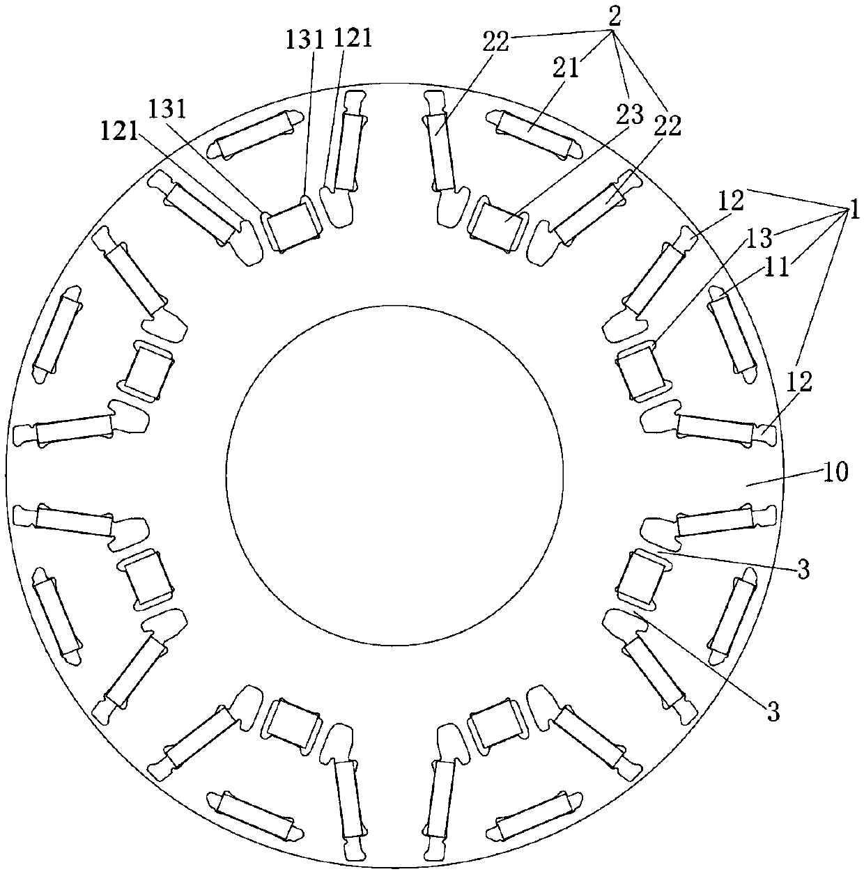
[0034] In this disclosure, unless stated to the contrary, the used orientation words such as "inner and outer" generally refer to the inner and outer of the outer contour of the motor rotor, and "circumferential and radial" refer to the outer contour of the motor rotor. Circumferential direction, radial direction, "cross section" mentioned in the present disclosure refers to the section shown in the direction of the corresponding drawing.

[0035] The present disclosure provides a motor rotor, a motor and an electric vehicle, wherein the motor can be a permanent magnet synchronous motor, etc., for example, it can be a image 3 Multi-pole permanent magnet syn...


PUM


Abstract

The invention relates to a motor rotor, a motor and an electric vehicle. The motor rotor comprises a rotor core with rotor punching sheets and magnetic steel groove sets which are arranged on the rotor punching sheets at intervals in the circumferential direction, wherein a first magnetic steel groove and a third magnetic steel groove in each magnetic pole groove set are arranged into structures which are respectively symmetrical about the radial center line along the circumferential direction; the pair of second magnetic steel grooves are symmetrically arranged on the two sides of the first magnetic steel groove and the third magnetic steel groove at intervals relative to the radial center line; the pair of second magnetic steel grooves incline inwards in the radial direction in the direction close to each other; the third magnetic steel groove is located on the inner side of the first permanent magnet at an interval in the radial center line direction; the inner end of the second magnetic steel groove and the third magnetic steel grooves are oppositely arranged at an interval in the circumferential direction; and in the radial center line direction, the first outermost end of thethird magnetic steel groove is flush with the second outermost end of the second magnetic steel groove or located on the outer side of the second outermost end. Therefore, the total torque of the motor can be improved and the strength of the rotor punching sheet is improved.

Description

technical field [0001] The present disclosure relates to the technical field of motors, and in particular, to a motor rotor, a motor and an electric vehicle. Background technique [0002] Motors are widely used as driving devices in various technical fields. For example, they can be used as the driving motor of electric vehicles to realize the function of driving vehicles. Due to the limitations of the design, it is usually necessary to design a small-volume drive motor, and the small-volume drive motor uses too little magnetic steel due to the limited layout space, which reduces the air gap flux density and electromagnetic torque. In this regard, in order to meet the torque requirements of the motor, the torque of the motor can be increased by appropriately increasing the number of permanent magnets. However, most of the following problems exist in this way, that is, the rotor of the motor is partially The structure, especially at the position where the rotor punch corresp...

Claims


Application Information

Patent Timeline
IPC IPC(8): H02K1/27H02K21/02
CPCH02K1/2766H02K21/028H02K2213/03Y02T10/64
Inventor 马冰青吴施汛
Owner BYD CO LTD
Why Eureka
Try Eureka