Self-locked mesh assembly, cage with same and manufacturing method of cage
A self-locking and component technology, applied in fishing, application, animal husbandry, etc., can solve the problems of animals that are not easy to catch, falling out, not passing through the net port, and animals escaping, etc., to achieve fast restocking and capture capabilities Strong, benefit-enhancing effect
- Summary
- Abstract
- Description
- Claims
- Application Information
AI Technical Summary
Problems solved by technology
Method used
Image

Examples
Embodiment 1
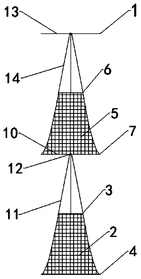
[0039] A self-locking mesh assembly such as figure 1 As shown, it includes the top ring 1, the second self-locking net and the first self-locking net arranged coaxially in sequence from top to bottom.
[0040] The first self-locking net includes a first net body 2 which is hollow inside. The top of the first net body 2 is provided with a first elastic lock 3 , and the bottom of the first net body 2 is provided with a first entrance 4 . The second self-locking net includes a second net body 5 which is hollow inside. The top of the second net body 5 is provided with a second elastic lock 6 , and the bottom of the second net body 5 is provided with a second inlet 7 . The first net body 2 is located at the first entrance 4 and is provided with a first ring 8 for supporting the first entrance 4 . The second net body 5 is located at the second entrance 7 and is provided with a second ring 9 for supporting the second entrance 7 .
[0041] During use, the self-locking net assembly...
Embodiment 2
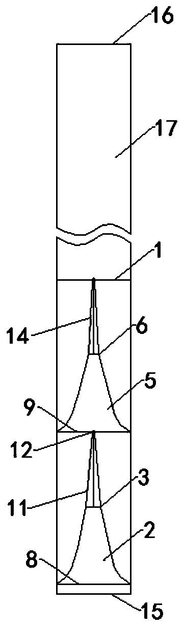
[0058] A self-locking floor cage, such as image 3 , Figure 4 As shown, including extranet 17. The outer net 17 is sleeved outside the self-locking net assembly of Embodiment 1. The outer net 17 is located at one end of the first entrance 4 and is provided with a ground cage entrance 15 . The outer net 17 is located at one end of the top ring 1 and is provided with a ground cage outlet 16, and the ground cage outlet 16 is provided with a control member for controlling the opening and closing of the ground cage outlet 16. Preferably, the control member is a rope. The first ring 8 , the second ring 9 and the top ring 1 are all detachably connected to the outer net 17 .
[0059] During use, the self-locking net assembly is placed in the outer net 17, and the first circular ring 8, the second circular ring 9 and the top ring 1 are connected to the outer net 17 by other connectors such as ropes. Use the control to close the cage outlet 16.
[0060] During use, the animal ent...
Embodiment 3
[0062] A method for making a ground cage, comprising the steps of:
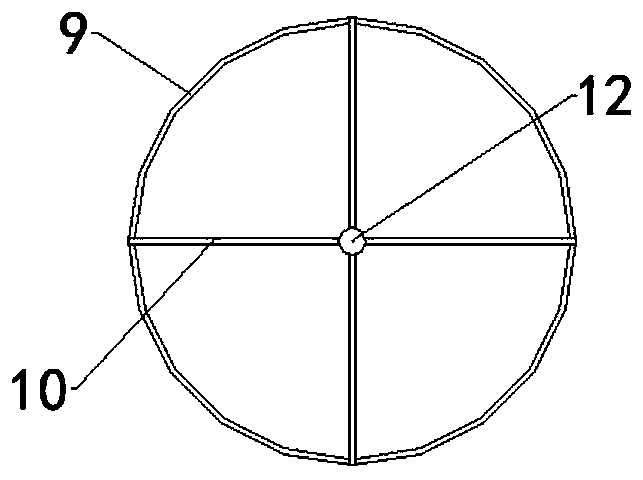
[0063] (1): Fix any side of the net tube on the first ring 8. The net cylinder is located at the position of the first circular ring 8 to form the first entrance 4 . 6 ropes are evenly distributed and connected on the other side of the cylinder, the upper parts of the 6 ropes are tied to form a knot 12, and 4 ropes are drawn out from the knot 12 for standby use to form the first self-locking net.
[0064] (2): Fix any side of another net tube on the second ring 9, and the net tube is located at the position of the second ring 9 to form the second entrance 7. Connect the 6 ropes evenly to the other side of the Yuantong, tie the upper parts of the 6 ropes to form a knot 12, draw out 4 ropes from the knot 12 for use, and form the second self-locking net.
[0065] (3): The 4 ropes reserved in step (1) are evenly distributed horizontally on the second ring 9, and the 4 ropes reserved in step (2) are evenly distr...
PUM
| Property | Measurement | Unit |
|---|---|---|
| The inside diameter of | aaaaa | aaaaa |
| The inside diameter of | aaaaa | aaaaa |
| The inside diameter of | aaaaa | aaaaa |
Abstract
Description
Claims
Application Information
 - R&D
- Intellectual Property
- Life Sciences
- Materials
- Tech Scout
- Unparalleled Data Quality
- Higher Quality Content
- 60% Fewer Hallucinations
Browse by: Latest US Patents, China's latest patents, Technical Efficacy Thesaurus, Application Domain, Technology Topic, Popular Technical Reports.
© 2025 PatSnap. All rights reserved.Legal|Privacy policy|Modern Slavery Act Transparency Statement|Sitemap|About US| Contact US: help@patsnap.com