Anastomat with pressure sensing device

A technology of a sensing device and a pressure sensor, which is applied in the field of staplers, can solve the problems of inconsistent nail formation, affect the operation efficiency, and large discrete effects, and achieve the effect of lowering the operation threshold, reducing the operation risk, and shortening the operation time.

Pending Publication Date: 2020-03-17
NANFANG HOSPITAL OF SOUTHERN MEDICAL UNIV +1
View PDF0 Cites 2 Cited by
  • Summary
  • Abstract
  • Description
  • Claims
  • Application Information

AI Technical Summary

Problems solved by technology

This requires the doctor to judge the reasonable degree of tissue compression completely based on experience during the process of closing and firing the stapler mouth, and cannot provide corresponding accurate tissue compression thickness according to the tissue characteristics of different patients.
However, the error in judging the thickness of tissue compression based on experience results in a large dispersion of postoperative effects in different patients. It is difficult to ensure that tissue compression can be in a reasonable nail-forming range for each operation. Once the tissue compression range is unreasonable, there will be Phenomena such as inconsistent nailing and secondary nailing, resulting in postoperative symptoms such as tissue leakage and tissue necrosis, which not only affect the efficiency of the operation, but also cause great pain to the patient

Method used


Image

  • Anastomat with pressure sensing device
  • Anastomat with pressure sensing device
  • Anastomat with pressure sensing device

Examples


Embodiment 1

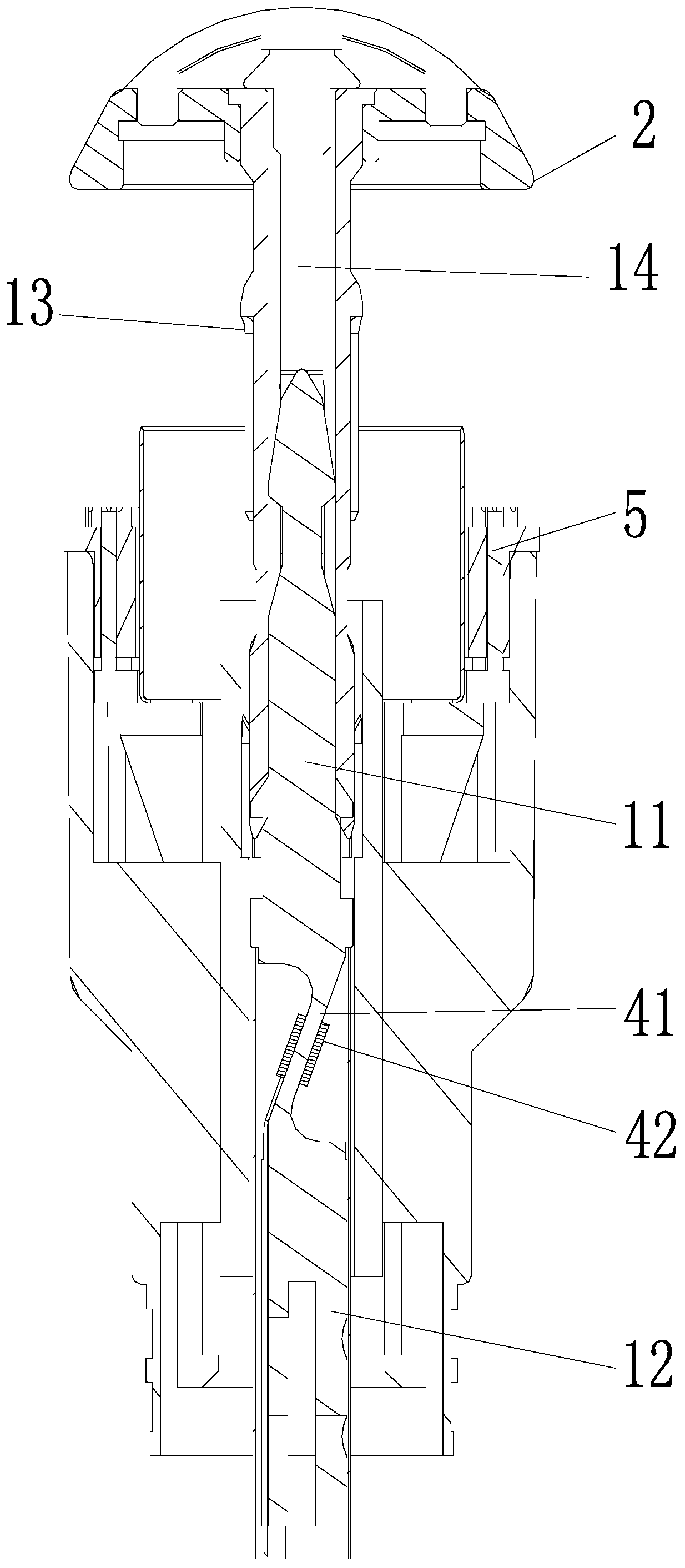
[0024] Such as Figure 1-5 Shown: The connection structure includes

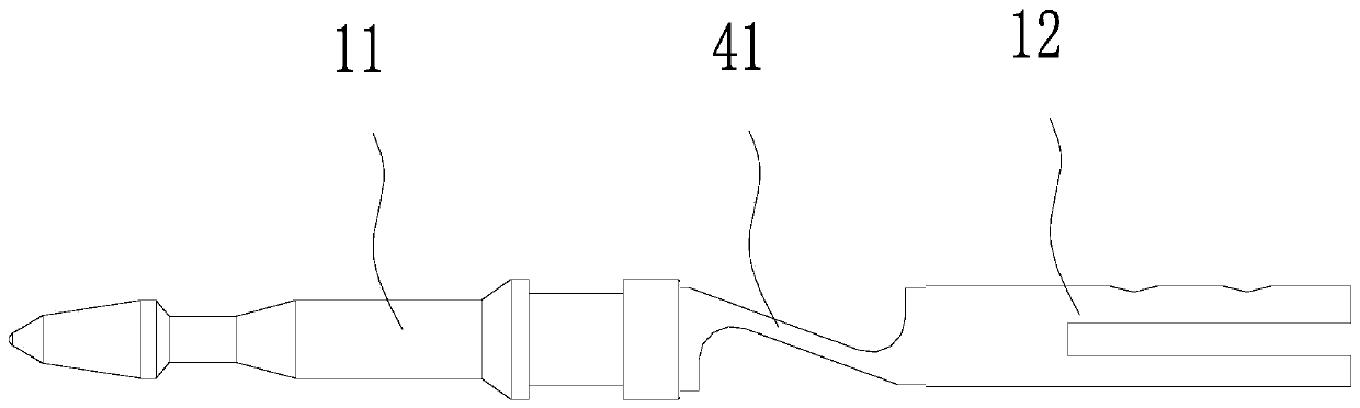
[0025] The linkage component A includes the puncture shaft A, the connecting piece A, and the screw rod A connected in sequence. The tail of the screw rod A is connected to the adjustment knob 3 and the linkage component A is controlled to move forward and backward through the adjustment knob 3;

[0026] The connecting pipe A13 is connected with the nail anvil 2 and has a reed A14 inside;

[0027] The puncture axis A is divided into an anterior puncture axis A11 and a rear puncture axis A12;

[0028] The front end of the front puncture shaft A11 is disassembled and connected with the snap reed A14;

[0029] The tail end of the rear puncture shaft A12 is connected to the connecting piece and the screw rod A;

[0030] The strain gauge pressure sensor is arranged between the front puncture axis A11 and the rear puncture axis A12 and is connected with them.

[0031] Wherein, the strain gauge pressure sensor ...

Embodiment 2

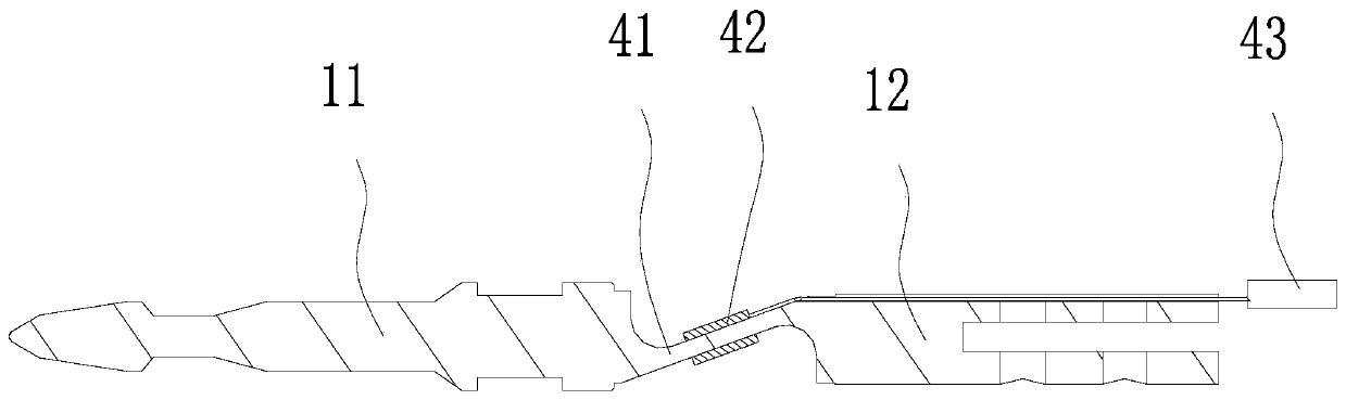
[0036] Such as Figure 6 Shown: The connection structure includes

[0037] The linkage component B includes the sequentially connected puncture shaft B16, connecting piece B, and screw B. The tail of the screw B is connected to the adjustment knob 3 and the linkage component B is controlled to move forward and backward through the adjustment knob 3;

[0038] The connecting pipe B17 is connected with the nail-resistance seat 2. The connecting pipe B17 is provided with a reed piece B18 that runs through the connecting pipe B17. The front end of the reed piece B18 extends into the cavity provided in the nail-resistance seat 2. The reed piece B18 is disassembled and connected with the puncture guide shaft B16;

[0039] The strain gauge pressure sensor is arranged in the cavity of the nail anvil 2 , and the strain gauge pressure sensor is respectively connected to the front end of the clip reed B18 and the nail anvil 2 .

[0040] Wherein, the strain gauge pressure sensor includes...

Embodiment 3

[0045] Such as Figure 7 Shown: The connection structure includes

[0046] The linkage component C includes the puncture shaft C, the connecting piece C, and the screw rod C19 connected in sequence, the tail of the screw rod C19 is connected with the adjustment knob 3 and the linkage component C is controlled to move forward and backward through the adjustment knob 3;

[0047] The connecting pipe C is connected to the nail anvil 2 and has a reed C inside, and the pipe structure is disassembled and connected to the guide shaft C through the reed C;

[0048] The strain gauge pressure sensor is arranged between the screw rod C19 and the adjusting knob 3 and is connected with the two.

[0049] in,

[0050] The strain gauge pressure sensor includes

[0051] The circular deformation piece 45 is connected to the front side of the adjustment knob 3 on the outer periphery, and the middle part is connected to the rear end of the screw rod C19, which deforms when it is stressed; , in...


PUM


Abstract

The invention discloses an anastomat with a pressure sensing device. The main body of the anastomat is the anastomat. A connecting structure with a strain type pressure sensor is arranged between a nail abutting seat and a rotary knob to achieve mutual linkage. When the rotary knob drives the nail abutting seat to move towards a nail bin and make contact with a barrier, the strain type pressure sensor detects the pressure of the barrier on the nail abutting seat. Compared with the prior art, the anastomat provided by the invention has the advantages that a doctor can accurately judge the optimal opportunity of an operation through provided visual pressure data or alarm, so that the operation threshold of the doctor is reduced; a reasonable tissue squeezing range is provided in an operation, so that the phenomena of inconsistent nailing, secondary nailing and the like are avoided; the operation success rate is improved; the operation risk is reduced; the operation time is shortened, andthe efficiency is improved; and the device can automatically or manually send the information of a postoperative patient to an enterprise cloud platform to carry out statistical analysis on later data, so that the device has an important significance for scientific research of surgical operations.

Description

technical field [0001] The invention relates to the field of medical instruments, in particular to a stapler with a pressure sensing device. Background technique [0002] The medical stapler is a medical device that is often used in performing surgical operations on the physiological tissues of the digestive tract. In general surgery, the stapler is often used to complete the cutting and closing functions of the tissue. The working principle of the stapler is to place the tissue between the staple cartridge and the anvil set, and to squeeze the tissue reasonably by adjusting the distance between the staple cartridge and the anvil set. When the distance between the staple cartridge and the anvil set When the safe range of effective suturing is reached, it is fired, and the U-shaped staples are compressed into a B-shape to suture the tissue. Small blood vessels can pass through the gaps of the B-shaped staples to ensure the blood supply of the anastomosis and distal tissues. ...

Claims


Application Information

Patent Timeline
Patent Type & Authority Applications(China)
IPC IPC(8): A61B17/115
CPCA61B17/115A61B2017/00022
Inventor 莫易凡林志雄林聪杰邱木旺苏占明
Owner NANFANG HOSPITAL OF SOUTHERN MEDICAL UNIV
Why Eureka
Try Eureka