Assembly type building prefabricated steel structure connecting and positioning machine and construction method

A steel structure and assembly technology, applied in the direction of building construction, construction, building materials processing, etc., can solve the problems of low working efficiency, uniformity, and inability to effectively ensure the feed rate of steel beams, etc., to improve work efficiency , The effect of facilitating reinforcement work

Inactive Publication Date: 2020-03-17
深圳龙琪绿建钢结构工程有限公司
View PDF8 Cites 15 Cited by
  • Summary
  • Abstract
  • Description
  • Claims
  • Application Information

AI Technical Summary

Problems solved by technology

[0003] However, the prefabricated building prefabricated steel structure connection and positioning machines in the market currently have the following problems during use. The connection and positioning of the beams makes the work efficiency of the device low. At the same time, the traditional machinery cannot effectively ensure the same feed rate of the steel beams, so repeated calibration is required during the operation; b. The existing prefabricated steel structure connection of prefabricated buildings When the positioning machine drives the steel beam to move, the contact surface between the steel beam and the clamping plate is prone to slipping, even if the butt joint between the steel beam and the steel column cannot be completed in one step

Method used


Image

  • Assembly type building prefabricated steel structure connecting and positioning machine and construction method
  • Assembly type building prefabricated steel structure connecting and positioning machine and construction method
  • Assembly type building prefabricated steel structure connecting and positioning machine and construction method

Examples


Embodiment Construction

[0028] In order to make the technical problems, technical solutions and beneficial effects to be solved by the present invention clearer, the present invention will be further described in detail below in conjunction with the accompanying drawings and embodiments. It should be understood that the specific embodiments described here are only used to explain the present invention, not to limit the present invention.

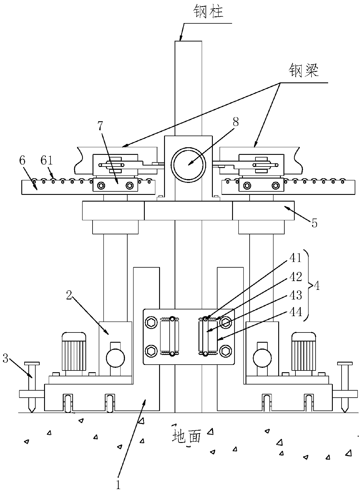
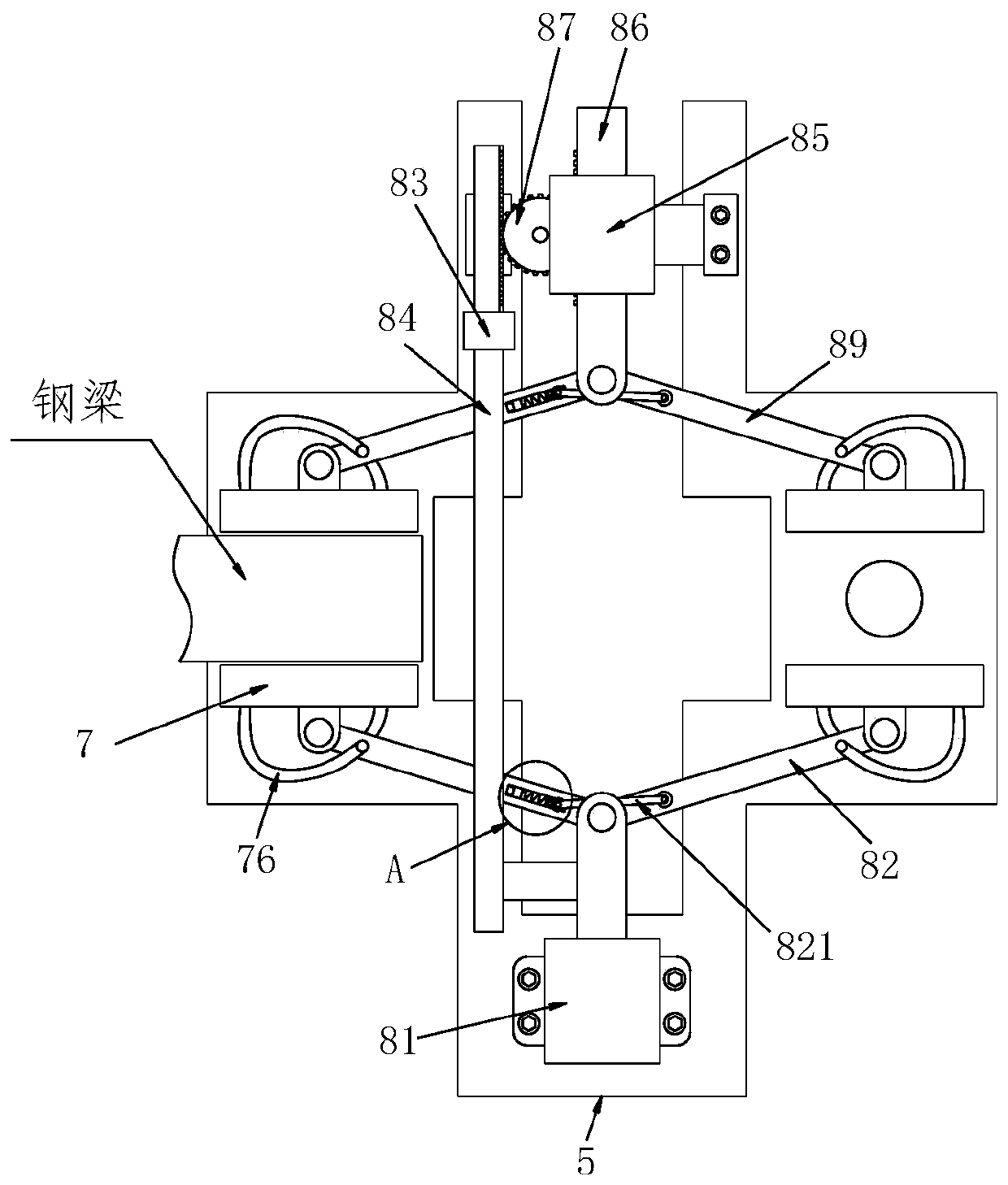
[0029] Such as Figure 1 to Figure 7 As shown, a prefabricated building prefabricated steel structure connecting and positioning mechanical equipment includes an L-shaped fixing seat 1, an electro-hydraulic push rod 2, a reinforcing rod 3, a connecting plate 4, a supporting seat 5, a placing seat 6, a clamping mechanism 7 and Drive mechanism 8, the quantity of described L-shaped fixed seat 1 is two, one end of two described L-shaped fixed seats 1 is fixed by connecting plate 4, and one side of L-shaped fixed seat 1 is provided with reinforcing rod 3, L-shaped fixed...


PUM


Abstract

The invention relates to an assembly type building prefabricated steel structure connecting and positioning machine and a construction method. The machine comprises L-shaped fixing seats, electric hydraulic pushing rods, reinforcing rods, connecting plates, a supporting seat, placing seats, clamping mechanisms and a driving mechanism, wherein the number of the L-shaped fixing seats is two, one ends of the two L-shaped fixing seats are fixed through the connecting plates, the reinforcing rods are arranged at one sides of the L-shaped fixing seats, the electric hydraulic pushing rods are arranged at the upper ends of the L-shaped fixing seats, the outer walls of the electric hydraulic pushing rods are welded with bearing trays, the supporting seat is arranged at the upper ends of the trays,the driving mechanism is arranged at the center of the top of the supporting seat, the placing seats are welded to the tops of the electric hydraulic pushing rods, and the clamping mechanisms are arranged at the two side walls of the placing seats. According to the machine and the method, two steel beams can be connected and positioned at the same time, so that the working efficiency is high, andthe feeding amount of the two steel beams can be guaranteed to be the same; and meanwhile, the multi-stage clamping mechanisms are adopted to fix the steel beams so that the contact surfaces between clamping structures and the steel beams cannot slip, and the repeated operations are not needed.

Description

technical field [0001] The invention relates to the technical field of building steel structure connection, in particular to a connection positioning machine and a construction method for prefabricated building prefabricated steel structures. Background technique [0002] Steel structure is a structure composed of steel materials, which is one of the main types of building structures. The structure is mainly composed of beam steel, steel column, steel truss and other components made of section steel and steel plate, and adopts rust removal and antirust processes such as silanization, pure manganese phosphating, washing and drying, and galvanizing. The components or components are usually connected by welds, bolts or rivets. Because of its light weight and easy construction, it is widely used in large factories, stadiums, super high-rises and other fields. During the construction of steel structure houses, since the steel beams have a certain height relative to the ground, ...

Claims


Application Information

Patent Timeline
Patent Type & Authority Applications(China)
IPC IPC(8): E04G21/18
CPCE04G21/1841
Inventor 张亚张晋源
Owner 深圳龙琪绿建钢结构工程有限公司
Why Eureka
Try Eureka