Screws with low twist-lock torque

A technology of locking twist and screw, applied in the direction of screws, bolts, threaded fasteners, etc., can solve the problems of increasing the difficulty of locking, increasing the twisting torque, and cracking the lock compound, so as to improve the occlusal stability, The effect of reducing twist lock torque and increasing cutting speed

Active Publication Date: 2021-07-13
TAIWAN SHAN YIN INT CO LTD
View PDF7 Cites 0 Cited by
  • Summary
  • Abstract
  • Description
  • Claims
  • Application Information

AI Technical Summary

Problems solved by technology

[0003] However, after actual use, it is found that when the screw 1 is locked on the lock, at the initial stage of locking, the drill tip 131 can only be used to squeeze into the lock until the lock part 13 After entering the lock, these screw teeth 14 can be connected to the lock part 13 to carry out the cutting operation of the lock, but these screw teeth 14 cannot effectively destroy the fibers of the lock, causing the fibers to be easily entangled On the screw 1, the torque of the twist lock is further increased, and at the same time, the chips generated by the subsequent locking are more likely to be hindered by the accumulated fibers and cannot be discharged in time, so that the screw 1 cannot continue to be screwed in, which increases The difficulty of locking. At this time, if the screw 1 continues to drill down to lock the lock, it is more likely to cause damage, passivation or breakage of the screw 1, or cause the lock to crack. Moreover, the screw 1 cannot effectively engage with the lock, so that the screw 1 is prone to loosening. When the screw 1 is pulled or vibrated by an external force, it is very easy to cause the screw 1 to loosen, shake or fall off. situation, which in turn leads to poor locking effect of the screw 1, which needs to be improved.

Method used


Image

  • Screws with low twist-lock torque
  • Screws with low twist-lock torque
  • Screws with low twist-lock torque

Examples


Embodiment Construction

[0043] The above and other technical content, features and efficacy of the present invention will be apparent from the preferred embodiments of the preferred embodiments of the drawings.

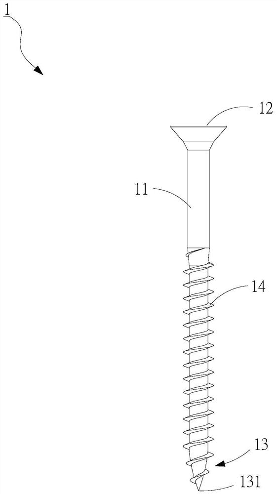
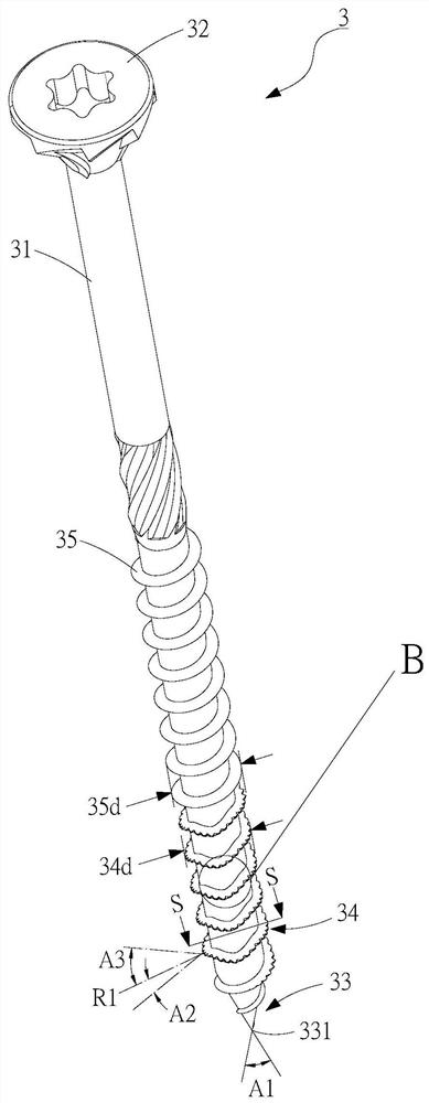
[0044] See figure 2 As shown, a preferred embodiment of the present invention, the screw 3 of the low rotary lock torque is includes a rod body 31, which is provided at the other end of the rod body 31 and the other end of the rod body 31 and opposite to screw head 32 of the locking portion 33, and a plurality of rods disposed on the body 31 and toward the cutting thread 33 of the locking portion 34 extends; wherein the locking portion 33 is formed a tapered drill point 331, and the lock engagement portion 33 meet at a tapered angle of the drill tip 331 extends outwardly formed A1 is preferably 22 to 26 degrees, while the present embodiment, the rod 35 further has a plurality of auxiliary thread 31, and the plurality The auxiliary screw 35 is provided with a complete dental state, and the above ...


PUM


Abstract

The present invention provides a screw with low twist-locking torque. The main feature is that a plurality of cutting threads are provided on the rod body, and each cutting thread is provided with a plurality of slots to form a first cutting edge and a second cutting edge. At the same time, the joint between the first cutting edge and the second cutting edge is provided with a groove to form two crests. Therefore, the cooperation of the first and second cutting edges with the crests is more conducive to rapid Reaming, while increasing the overall cutting speed, can also effectively cut the fibers of the lock, so as to avoid the fiber entanglement and hinder the lock, and greatly reduce the torque of the twist lock, and then cooperate with the grooves and the lock These slots moderately accommodate and hold down part of the chips, which is more helpful to improve the locking engagement between the screw and the lock, not only effectively increasing the pulling force, but also improving the engagement stability of the screw screwing in.

Description

Technical field [0001] The present invention relates to a non-locking member, particularly a screw with a low rotary lock torque. Background technique [0002] See figure 1 The well-known screw 1 includes a rod body 11, a screw 12, which is provided at one end of the rod body 11, is provided on the other end of the rod body 11 and is opposite to the bonding portion 13 of the screw 12, and a plurality of pieces of the rod 11 The screw 14 extends toward the locking portion 13; wherein the locking portion 13 is tapered to form a drill pointer 131; when used, first pressurize the drill tip 131 in a lock compound (not shown) On the surface, a rotary torque is applied to the screw 12 to carry through the drill tip 131 to drill on the latch by the drill tip 131, and the locking portion 13 is gradually screwed into the lock. After that, the twisting 14 continues the locking portion 13 to cut the locking member, by linking the rod body 11 with the cutting of the twisting 14, thereby compl...

Claims


Application Information

Patent Timeline
Patent Type & Authority Patents(China)
IPC IPC(8): F16B25/02F16B23/00
CPCF16B25/0052F16B25/0084F16B25/103
Inventor 苏国材苏振荣
Owner TAIWAN SHAN YIN INT CO LTD
Why Eureka
Try Eureka