Rotating electrical machine

A technology for rotating electrical machines and rotors, applied in the field of rotating electrical machines, can solve problems such as waste and material yield decline

Active Publication Date: 2020-03-17
MITSUBISHI ELECTRIC CORP
View PDF6 Cites 0 Cited by
  • Summary
  • Abstract
  • Description
  • Claims
  • Application Information

AI Technical Summary

Problems solved by technology

[0002] In the rotor of a conventional rotating electric machine, the rotor core is produced by stacking circular-shaped punched s...

Method used


Image

  • Rotating electrical machine
  • Rotating electrical machine
  • Rotating electrical machine

Examples


Embodiment approach 1

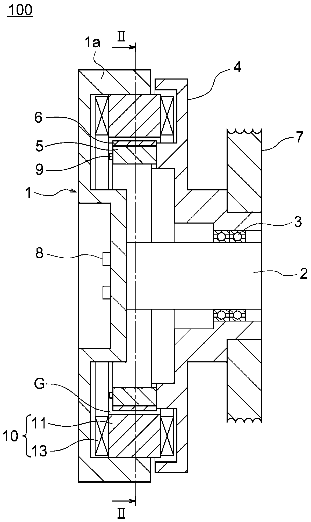
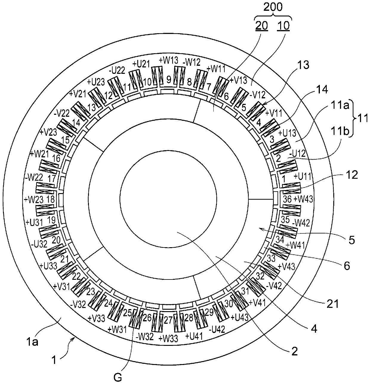
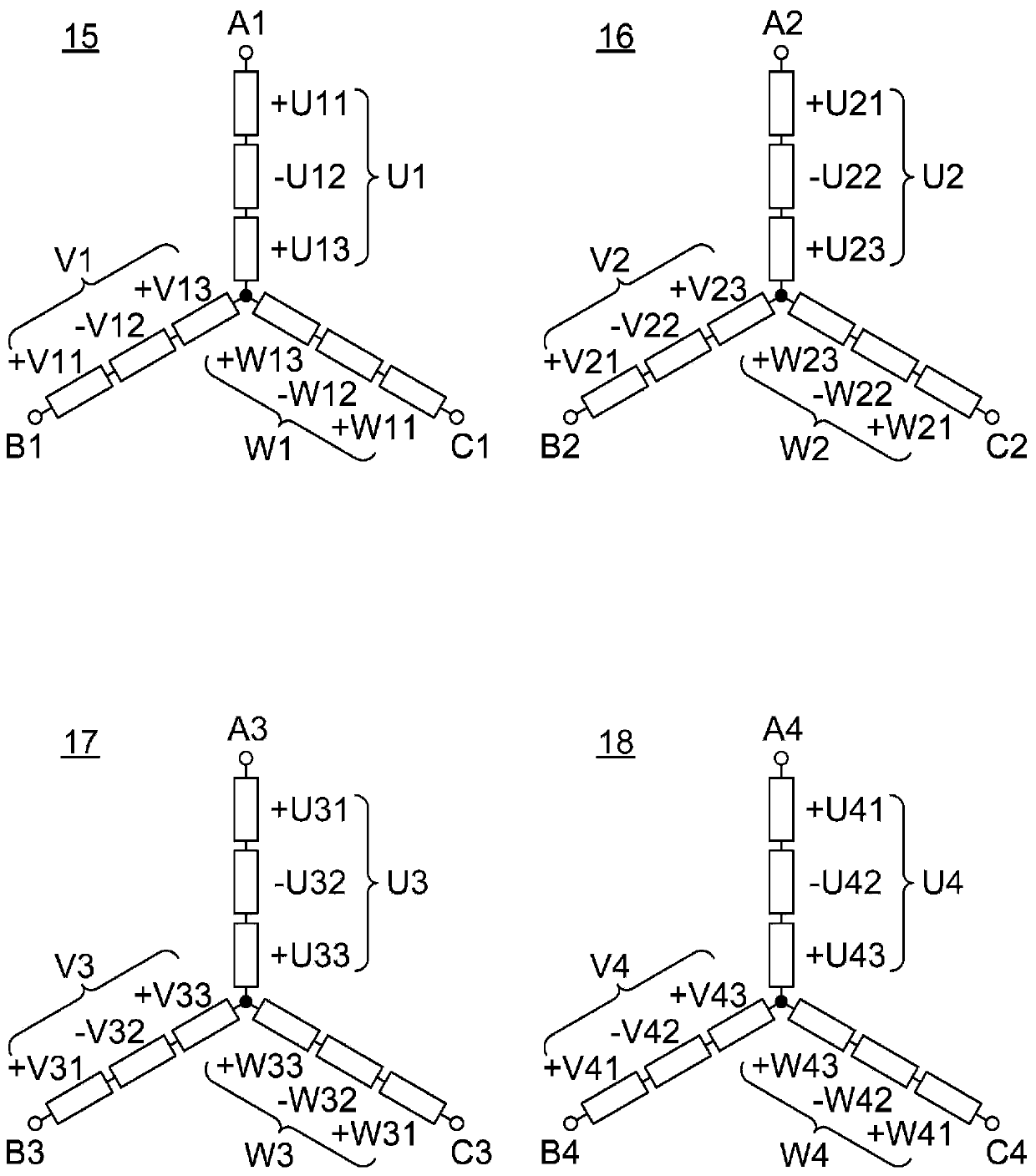
[0044] figure 1 It is a sectional view showing a hoisting machine of an elevator to which the rotating electric machine according to Embodiment 1 of the present invention is applied, figure 2 yes figure 1 II-II arrow sectional view, image 3 is a wiring diagram of a stator coil in the rotating electrical machine according to Embodiment 1 of the present invention, Figure 4 It is a sectional view showing a rotating electric machine of a comparative example. In addition, in figure 2 , 4 In , hatching is omitted for convenience. In addition, in figure 2 and Figure 4 Among them, 1 to 36 are the tooth numbers marked on the teeth in the counterclockwise order.

[0045] exist figure 1 Among them, the traction machine 100 has: a stator frame 1; a stator 10, which is fixed to the stator frame 1, has an annular stator core 11 and a stator coil 13 installed on the stator core 11; a shaft 2, which is fixed to the stator The frame 1 is arranged at the axial center of the stat...

Embodiment approach 2

[0072] Figure 5 is a perspective view showing a rotor core of a rotating electrical machine according to Embodiment 2 of the present invention, Image 6 It is a schematic diagram showing the magnetic circuit generated by the permanent magnets in the rotor core of the electric rotating machine according to Embodiment 2 of the present invention.

[0073] exist Figure 5 Among them, the rotor core 5A is an annular laminated core having a predetermined thickness. On the outer peripheral portion of the rotor core 5A, 40 magnetic poles 6A made of permanent magnets and magnetic poles 6B made of soft magnetic materials are alternately arranged at equiangular intervals in the circumferential direction. The rotor core 5A is configured in an annular shape by arranging five split cores 21A in the circumferential direction. The split iron core 21A is formed by dividing the rotor iron core 5A into five equal parts in the circumferential direction at the center position of the magnetic p...

Embodiment approach 3

[0088] Figure 7 It is a perspective view showing the rotor core of the rotating electrical machine according to Embodiment 3 of the present invention.

[0089] exist Figure 7 In the figure, dovetail grooves and dovetail bodies are omitted on both side surfaces in the circumferential direction of the split iron core 21B. The rotor core 5B is constituted by arranging the five split cores 21B in an annular shape in the circumferential direction. The five split iron cores 21B arranged in an annular shape are integrally connected by curing the adhesive in a state where the circumferential side surfaces coated with the adhesive are butted against each other.

[0090] In Embodiment 3, it is configured in the same manner as in Embodiment 2 above, except that the adjacent split iron cores 21B are connected by an adhesive.

[0091] Therefore, also in Embodiment 3, the same effects as in Embodiment 2 described above are obtained.


PUM


Abstract

The present invention achieves a rotating electrical machine that can suppress torque ripple increases caused by division of a rotor core. This rotating electrical machine is provided with: an annularcore back; a stator including a plurality of teeth, each of which protrudes in the radial direction from the core back and which are arrayed in the circumferential direction, with slots being formedbetween the teeth that are adjacent in the circumferential direction; and a rotor that includes an annular rotor core that is disposed rotatably and also coaxially with the stator with a magnetic gaptherebetween, and a plurality of magnetic poles disposed on the rotor core in the circumferential direction. The rotor core includes a plurality of divided cores divided in the circumferential direction by division surfaces, and the number of divisions of the rotor core are different from a divisor or a multiple of the largest common denominator of the number of poles of the rotor and the number of slots.

Description

technical field [0001] The present invention relates to a rotating electrical machine applied to, for example, a motor of a hoisting machine of an elevator. Background technique [0002] In the rotor of a conventional rotating electrical machine, the rotor core is produced by stacking circular punched steel plates, and the inner peripheral part of the punched circular steel plates is wasted, and the material yield decreases. [0003] In view of such a situation, a conventional rotating electrical machine has been proposed in which a ring-shaped rotor core is produced by arranging split cores in a circumferential direction, and the yield rate of the material of the rotor core is improved. It is produced from a steel plate punched out in an arc shape (for example, refer to Patent Documents 1 and 2). [0004] prior art literature [0005] patent documents [0006] Patent Document 1: Japanese Patent Laid-Open No. 2012-249386 [0007] Patent Document 2: Japanese Patent Laid-O...

Claims


Application Information

Patent Timeline
IPC IPC(8): H02K1/27
CPCH02K3/28H02K1/2746H02K2213/03H02K1/276H02K1/2766H02K21/14H02K1/14H02K1/16H02K1/28H02K15/03
Inventor 冈崎广大泷口隆一山口信一内村智也加岛俊大梅田隆司
Owner MITSUBISHI ELECTRIC CORP
Why Eureka
Try Eureka