rotating electrical machine
A technology of rotating electrical machines and rotors, applied in the field of rotating electrical machines, can solve the problems of material yield reduction and waste, and achieve the effect of suppressing the increase of torque ripple
- Summary
- Abstract
- Description
- Claims
- Application Information
AI Technical Summary
Problems solved by technology
Method used
Image
Examples
Embodiment approach 1
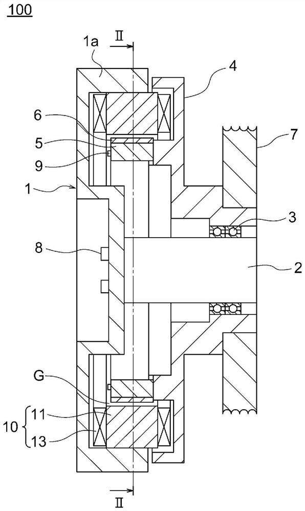
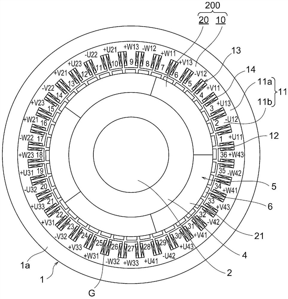
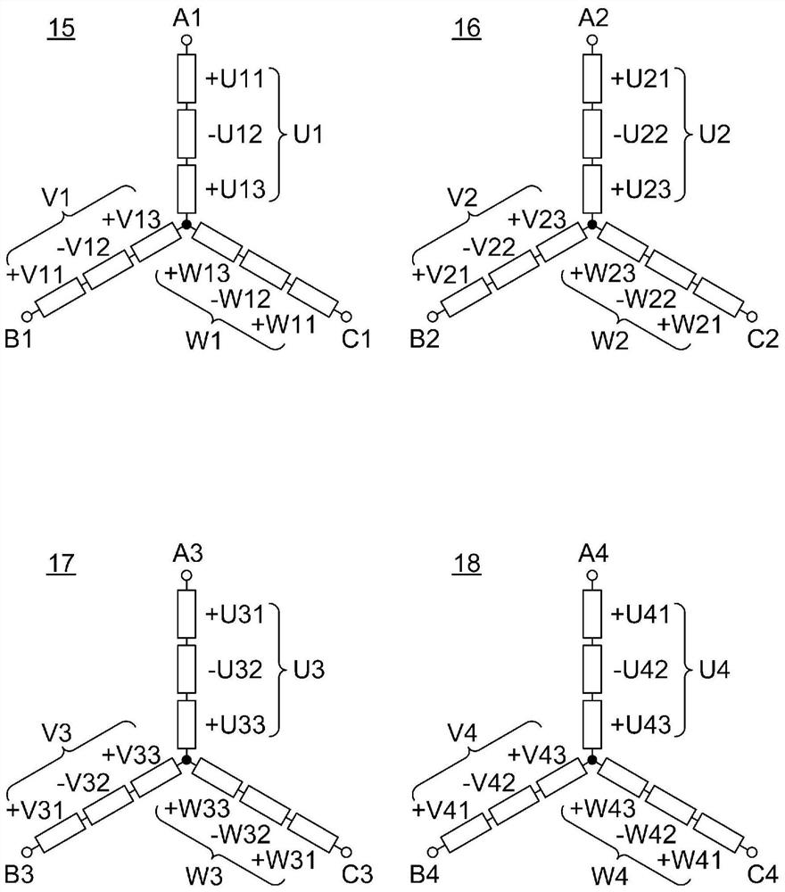
[0044] figure 1 It is a sectional view showing a hoisting machine of an elevator to which the rotating electric machine according to Embodiment 1 of the present invention is applied, figure 2 yes figure 1 II-II arrow sectional view, image 3 is a wiring diagram of a stator coil in the rotating electrical machine according to Embodiment 1 of the present invention, Figure 4 It is a sectional view showing a rotating electric machine of a comparative example. In addition, in figure 2 , 4 In , hatching is omitted for convenience. In addition, in figure 2 and Figure 4 Among them, 1 to 36 are the tooth numbers marked on the teeth in the counterclockwise order.
[0045] exist figure 1 Among them, the traction machine 100 has: a stator frame 1; a stator 10, which is fixed to the stator frame 1, has an annular stator core 11 and a stator coil 13 installed on the stator core 11; a shaft 2, which is fixed to the stator The frame 1 is arranged at the axial center of the stat...
Embodiment approach 2
[0072] Figure 5 is a perspective view showing a rotor core of a rotating electrical machine according to Embodiment 2 of the present invention, Figure 6 It is a schematic diagram showing the magnetic circuit generated by the permanent magnets in the rotor core of the electric rotating machine according to Embodiment 2 of the present invention.
[0073] exist Figure 5 Among them, the rotor core 5A is an annular laminated core having a predetermined thickness. On the outer peripheral portion of the rotor core 5A, 40 magnetic poles 6A made of permanent magnets and magnetic poles 6B made of soft magnetic materials are alternately arranged at equiangular intervals in the circumferential direction. The rotor core 5A is configured in an annular shape by arranging five split cores 21A in the circumferential direction. The split iron core 21A is formed by dividing the rotor iron core 5A into five equal parts in the circumferential direction at the center position of the magnetic ...
Embodiment approach 3
[0088] Figure 7 It is a perspective view showing the rotor core of the rotating electrical machine according to Embodiment 3 of the present invention.
[0089] exist Figure 7 In the figure, dovetail grooves and dovetail bodies are omitted on both side surfaces in the circumferential direction of the split iron core 21B. The rotor core 5B is constituted by arranging the five split cores 21B in an annular shape in the circumferential direction. The five split iron cores 21B arranged in an annular shape are integrally connected by curing the adhesive in a state where the circumferential side surfaces coated with the adhesive are butted against each other.
[0090] In Embodiment 3, it is configured in the same manner as in Embodiment 2 above, except that the adjacent split iron cores 21B are connected by an adhesive.
[0091] Therefore, also in Embodiment 3, the same effects as in Embodiment 2 described above are obtained.
PUM
 Abstract
Description
Claims
Application Information
 - R&D
- Intellectual Property
- Life Sciences
- Materials
- Tech Scout
- Unparalleled Data Quality
- Higher Quality Content
- 60% Fewer Hallucinations
Browse by: Latest US Patents, China's latest patents, Technical Efficacy Thesaurus, Application Domain, Technology Topic, Popular Technical Reports.
© 2025 PatSnap. All rights reserved.Legal|Privacy policy|Modern Slavery Act Transparency Statement|Sitemap|About US| Contact US: help@patsnap.com


