Rotor, motor and electrical device including the motor

a technology of electrical devices and motors, applied in the direction of dynamo-electric machines, magnetic circuit rotating parts, magnetic circuit shapes/forms/construction, etc., can solve the problems of reducing output torque, affecting the stability of torque output, and difficulty in designing control algorithms, so as to increase torque ripple, increase noise and heat energy, increase torque ripple

Active Publication Date: 2019-05-30
NIDEC CORP
View PDF16 Cites 1 Cited by
  • Summary
  • Abstract
  • Description
  • Claims
  • Application Information

AI Technical Summary

Benefits of technology

[0008]The inventors of preferred embodiments of the present invention discovered that a shape and a position of a flux barrier causes a reluctance in an air gap to have discontinuous or dramatic changes, such that a component of multiple harmonics may be generated spatially. The greater a harmonic component is, the more a torque ripple is increased. Increased torque ripple causes a motor to generate increased noise and heat energy, which affects the stability of a torque output and difficulty in designing a control algorithm. Torque ripple can be reduced by changing a structure of a stator slot or by an inclined rotor structure change. However, changing a structure of a stator slot or an inclination of the rotor structure also reduces an output torque, and the ways in which a shape change may adjust an amplitude of a structure of a stator slot and a rotor inclination angle are very limited such that an overall proportion of reducing a torque ripple also is limited and a torque ripple cannot be reduced significantly.
[0009]Preferred embodiments of the present invention provide a rotor, a motor, and an electrical device including the motor, with which it is possible to reduce a torque ripple while an output torque is kept unchanged.
[0020]An advantageous effect of the preferred embodiments of the present disclosure is that, with the structure of the motors of the preferred embodiments of the present disclosure, a torque ripple is able to be reduced significantly and the same output torque is able to be maintained such that the overall performance of the motor is improved.

Problems solved by technology

Increased torque ripple causes a motor to generate increased noise and heat energy, which affects the stability of a torque output and difficulty in designing a control algorithm.
However, changing a structure of a stator slot or an inclination of the rotor structure also reduces an output torque, and the ways in which a shape change may adjust an amplitude of a structure of a stator slot and a rotor inclination angle are very limited such that an overall proportion of reducing a torque ripple also is limited and a torque ripple cannot be reduced significantly.

Method used


Image

  • Rotor, motor and electrical device including the motor
  • Rotor, motor and electrical device including the motor
  • Rotor, motor and electrical device including the motor

Examples


embodiment 1

Preferred Embodiment 1

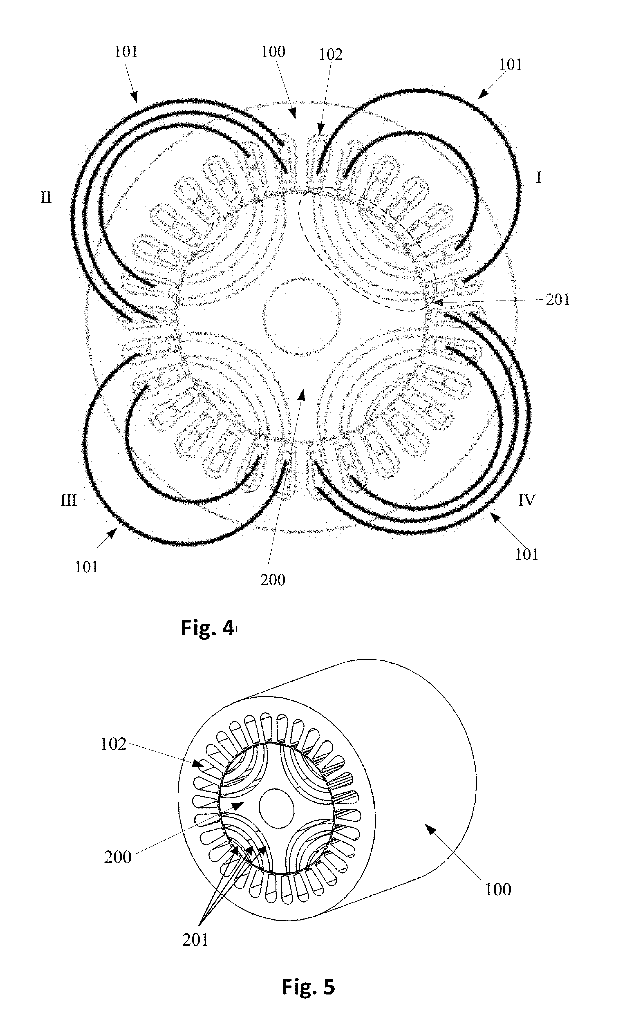
[0040]The present preferred embodiment of the present invention provides a motor. FIG. 4 is an axial plan view schematic diagram of the motor, and FIG. 5 is a stereoscopic schematic diagram of the motor.

[0041]As shown in FIGS. 4 and 5, the motor preferably includes: a stator 100 including wound multiphase coils 101 and stator slots 102 that accommodate the multiphase coils 101; and a rotor 200 provided at an inner side of the stator 100. A plurality of poles are provided in a direction of rotation, a plurality of sets of flux barriers 201 being provided on the rotor 200, each pole corresponding to a set of flux barriers.

[0042]In the illustrative examples of FIGS. 4 and 5, four poles (as shown by I, II, III, IV in FIG. 4) are provided in a direction of rotation of the rotor 200 such that four sets of flux barriers 201 are provided on the rotor 200. However, the present preferred embodiment is not limited to this, and the number of the poles and the number of set...

embodiment 2

Preferred Embodiment 2

[0060]The present preferred embodiment of the present invention provides a rotor, a plurality of poles being provided in a direction of rotation of the rotor, a plurality of sets of flux barriers being provided on the rotor, each pole corresponding to a set of flux barriers.

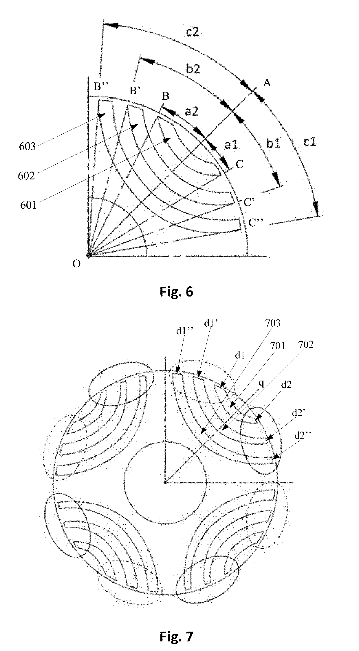
[0061]In one implementation of the present preferred embodiment, included angles between lines from two points on a circumferential edge of at least one flux barrier respectively to the center of the rotor and the central line are unequal in a set of flux barriers corresponding to each pole, by taking a line extending from the center of the rotor to a direction with the maximum reluctance as a central line.

[0062]In another implementation of the present preferred embodiment, in a set of flux barriers corresponding to each pole, widths of circumferential edges of at least one flux barrier in a circumferential direction are unequal by taking a line extending from the center of the rotor to a di...

embodiment 3

Preferred Embodiment 3

[0065]The present preferred embodiment of the present invention provides an electrical device including the motor of Preferred Embodiment 1, further including other conventional components. The present preferred embodiment does not make limitations on structures, setting modes and functions of these conventional components, and the related arts can be referenced.

[0066]In the present preferred embodiment, based on the structure of the motor of Preferred Embodiment 1, with a non-integer slot-pole ratio design or with the non-integer slot-pole ratio design matched with an asymmetric rotor design, a torque ripple is able to be reduced significantly and the same output torque is able to be maintained, and the overall performance of the motor is improved.

[0067]In the present preferred embodiment, the electrical device may be any electrical device using a motor, for example, an automobile transmission using a motor. However, the present preferred embodiment is not lim...


PUM


Abstract

A motor includes a stator including wound multiphase coils and stator slots that accommodate the multiphase coils, and a rotor provided at an inner side of the stator. Poles are provided in a direction of rotation, and sets of flux barriers are provided on the rotor, each of the poles respectively corresponding to a set of the flux barriers. A ratio between a total number of the stator slots and a product of a total number of poles of the rotor and a phase number of the multiphase coils is a non-integer. With the structure of the motor, a torque ripple is reduced while an output torque is kept unchanged.

Description

CROSS REFERENCE TO RELATED APPLICATIONS[0001]This application claims the benefit of priority to Chinese Patent Application No. 201711239739.8 filed on Nov. 30, 2017. The entire contents of this application are hereby incorporated herein by reference.BACKGROUND OF THE INVENTION1. Field of the Invention[0002]The present invention relates to motors and, particularly to a rotor, a motor, and an electrical device including the motor.2. Description of the Related Art[0003]In a conventional motor, in order to reduce torque ripples, rotors deflect radially. For a synchronous reluctance motor, different rotor structures are stacked to reduce torque ripples and keep an output torque unchanged.[0004]FIG. 1 is a sectional view and an exploded view of a rotor stacked by different flux barrier structures. As shown in FIG. 1, the whole rotor is formed by stacking two rotors having different flux barrier structures, i.e., rotor A and rotor B. A main difference between rotor A and rotor B lies in th...

Claims


Application Information

Patent Timeline
Patent Type & Authority Applications(United States)
IPC IPC(8): H02K1/24H02K19/10
CPCH02K1/246H02K19/103H02K29/03H02K1/165
Inventor YEN, SHENG-CHANLIN, HSIN-NANHSU, YU-WEILIU, CHENG-TSUNG
Owner NIDEC CORP
Why Eureka
Try Eureka