
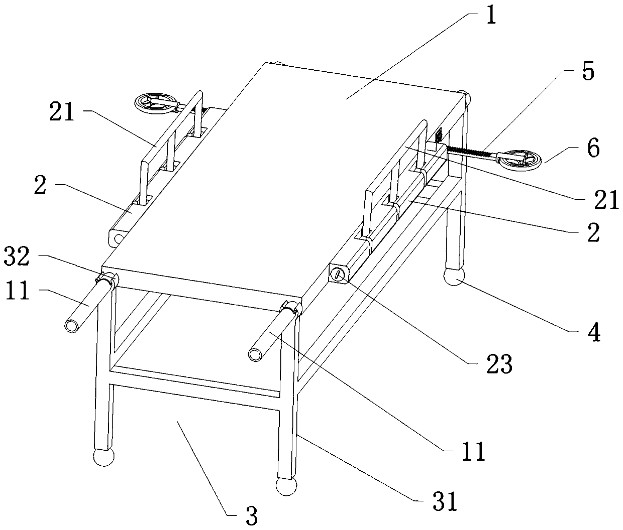
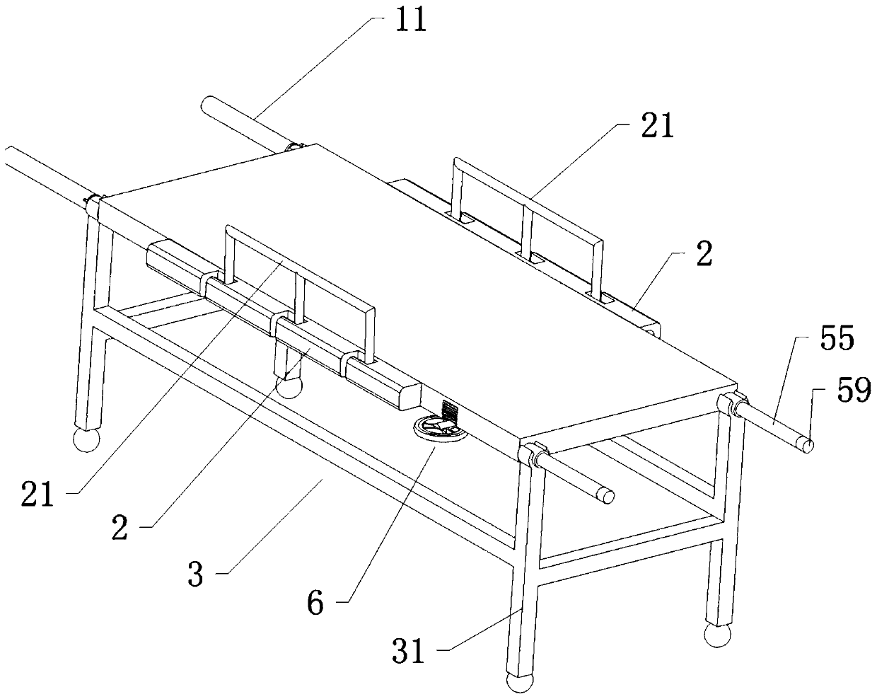
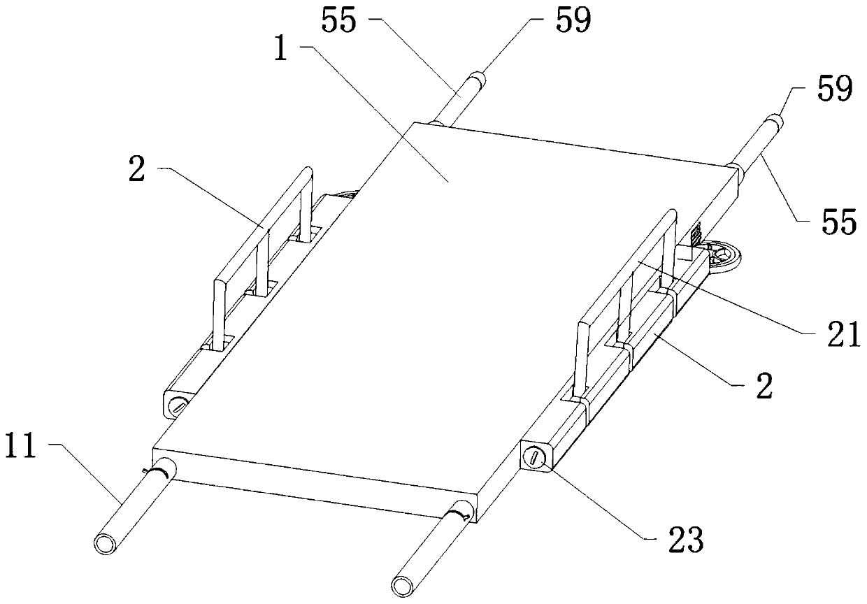
Stretcher trolley convenient for patient transferring

A technology for a stretcher car and a patient, which is applied in the field of stretcher cars, can solve the problems that a single person cannot transport patients, is inconvenient to transport patients, and is difficult to walk on a stretcher car, and achieves the effects of saving human resources, simple and convenient operation, and reasonable structure.

Pending Publication Date: 2020-03-20
周燕
View PDF0 Cites 4 Cited by
  • Summary
  • Abstract
  • Description
  • Claims
  • Application Information

AI Technical Summary

Problems solved by technology

[0002] In hospitals, stretcher trolleys are one of the most commonly used equipment for transferring patients. The current stretcher trolleys have a single structure and function, which cannot meet the use of stretcher trolleys in some environments, such as the usual stretcher trolley bed and the bottom of the bed. The support of the stretcher cannot be disassembled. In some special terrain environments, it is difficult for the stretcher to walk, and it is inconvenient to transport patients. For example, the usual stretcher requires more than two staff members to operate. At present, it is generally the same as the door used in the main entrance. Automatic return door, when the stretcher trolley passes the return door, a staff member needs to open the door before the stretcher trolley can enter. In this case, when the staff is tense, a single person cannot transport the patient. Such a stretcher trolley can be disassembled and used. The stretcher trolley that can be pushed by one person does not need other personnel to open the door when passing the return door

Method used


Image

  • Stretcher trolley convenient for patient transferring
  • Stretcher trolley convenient for patient transferring
  • Stretcher trolley convenient for patient transferring

Examples


Embodiment

[0044] Example: such as Figure 1 to Figure 16As shown, a stretcher cart convenient for transferring patients includes a couch 1 with a bracket 3 at the bottom, a roller 4 at the bottom of the bracket 3, a detachable connection between the couch 1 and the bracket 3, and two ends of the couch 1 respectively. There are a handle tube 11 and a fixed tube 14, auxiliary blocks 2 are arranged on both sides of the reclining board 1, the auxiliary block 2 is equipped with a guardrail 21, the auxiliary block 2 is provided with an insertion cavity 27, the port of the insertion cavity 27 is equipped with a cover plug 23, 27 is arranged along auxiliary block 2 body, and auxiliary block 2 is provided with slot 24, and slot 24 is perpendicular to deck 1 body and is arranged, and slot 24 runs through auxiliary block 2, and slot 24 is connected with inserting cavity 27, and auxiliary block 2 side The wall is provided with a gap 25, the gap 25 communicates with the slot 24 and the insertion cav...


PUM


Abstract

The invention provides a stretcher trolley convenient for patient transferring. The stretcher trolley includes lying board; the top of the lying board is provided with guard bars, and the bottom of the lying board is provided with support legs with wheels; handle cylinders are arranged on the sidewall on one end of the lying board; sliding sleeves are arranged on the end, away from the handle cylinders, at the bottom of the lying board; racks are installed in the sliding sleeves; gear grooves are arranged in the sidewall of the lying board; connecting columns are in threaded connection with the ends, away from the center of the lying board, of the racks; buffer wheels are installed on the connecting columns; the two sides of the lying board are provided with sliding cavities; ball screws are inserted into the sliding cavities; ball nuts are installed on the ball screws; gears meshing with the racks are installed on the ball nuts and are located in the gear grooves; one ends of the ballscrews are connected to handles, and the other ends of the ball screws are connected to sliding rods; and handle sleeves are provided with fixing devices that can fix the sliding rods. The stretchertrolley can be operated by only one worker when passing through the return doors of a hospital, so that the stretcher trolley is simple and convenient in operation and can effectively save manpower; and in conclusion, the stretcher trolley is reasonable in framework, simple in operation and suitable for popularization and application.

Description

technical field [0001] The invention relates to a stretcher cart which is convenient for transferring patients. Background technique [0002] In hospitals, stretcher trolleys are one of the most commonly used equipment for transferring patients. The current stretcher trolleys have a single structure and function, which cannot meet the use of stretcher trolleys in some environments, such as the usual stretcher trolley bed and the bottom of the bed. The support of the stretcher cannot be disassembled. In some special terrain environments, it is difficult for the stretcher to walk, and it is inconvenient to transport patients. For example, the usual stretcher requires more than two staff members to operate. At present, it is generally the same as the door used in the main entrance. Automatic return door, when the stretcher trolley passes the return door, a staff member needs to open the door before the stretcher trolley can enter. In this case, when the staff is tense, a single...

Claims


Application Information

Patent Timeline
IPC IPC(8): A61G1/02A61G1/04A61G1/048
CPCA61G1/02A61G1/04A61G1/048
Inventor 周燕刘瀚凌韦佳利
Owner 周燕
Learn More