Electric pedal sewing machine

A sewing machine and pedal technology, applied in the field of clothing sewing, can solve the problems of inconvenient and labor-saving carrying and moving, inability to arrange and store wires, and increase the space occupied by equipment, so as to achieve convenient carrying and labor-saving, tidy equipment and improved safety sexual effect

Inactive Publication Date: 2020-03-20
广西万盛服装服饰有限公司
View PDF0 Cites 0 Cited by
  • Summary
  • Abstract
  • Description
  • Claims
  • Application Information

AI Technical Summary

Problems solved by technology

[0002] The sewing machine is a common machine for sewing clothes. With the development of science and technology, the traditional manual pedal sewing machine is gradually replaced by the electric sewing machine. Compared with the traditional pedal sewing machine, the electric sewing machine is more convenient and labor-saving, and more Accurate, can also speed up the sewing speed, improve production efficiency, the existing electric pedal sewing machine has been relatively perfect in terms of structure and function, but there is still room for improvement in the process of use; first, the fabric needs to be The sewing needle advances gradually, but the existing electric sewing machine cannot ensure that the cloth will not deviate from the moving track when it is advanced, resulting in uneven and irregular stitches; secondly, the equipment is an electrical equipment, and the wires cannot be obtained more properly. The organization and storage of the device make it vulnerable to unnecessary wear and tear; finally, the carrying and moving of the device is not convenient and labor-saving, and the traditional handle will increase the space occupied by the device as a whole

Method used


Image

  • Electric pedal sewing machine
  • Electric pedal sewing machine
  • Electric pedal sewing machine

Examples


Embodiment Construction

[0023] The technical solutions in the embodiments of the present invention will be clearly and completely described below in conjunction with the accompanying drawings in the embodiments of the present invention. Obviously, the described embodiments are only a part of the embodiments of the present invention, rather than all the embodiments. Based on the embodiments of the present invention, all other embodiments obtained by those of ordinary skill in the art without creative work shall fall within the protection scope of the present invention.

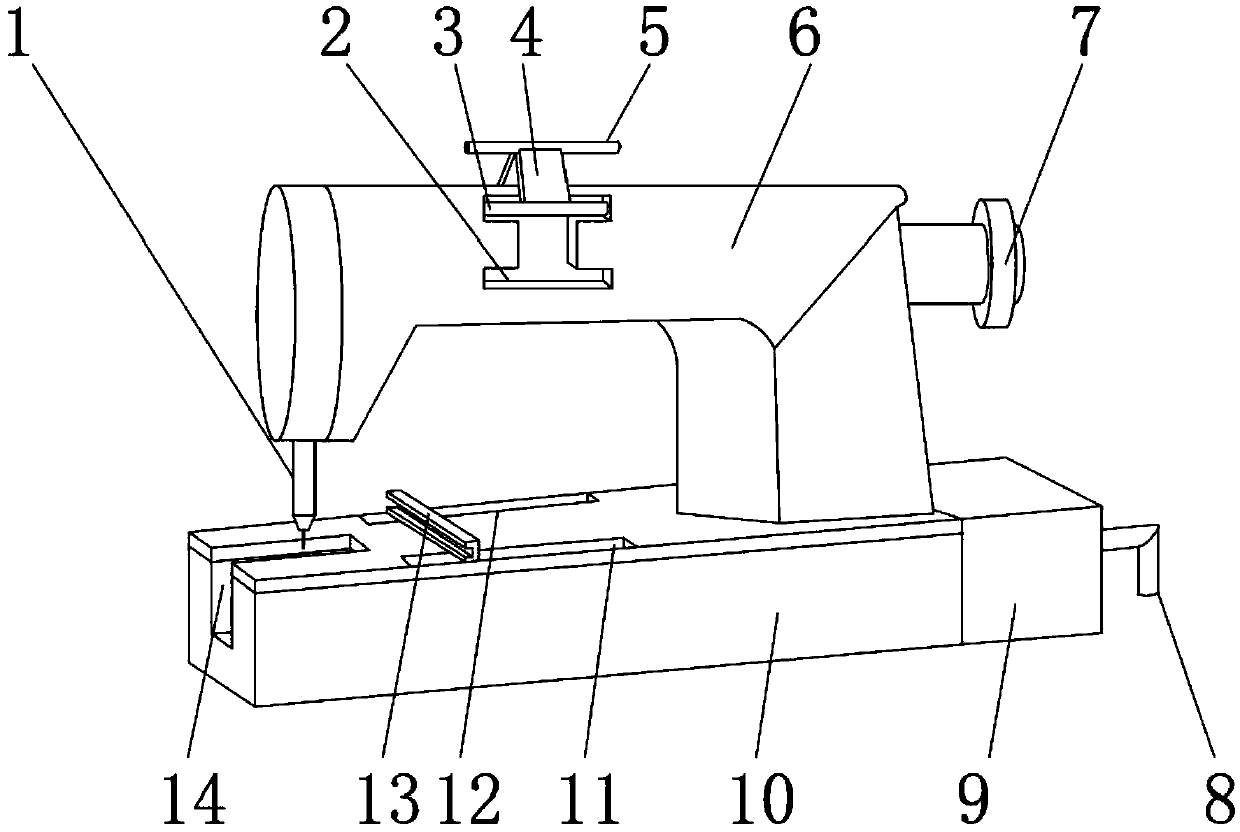
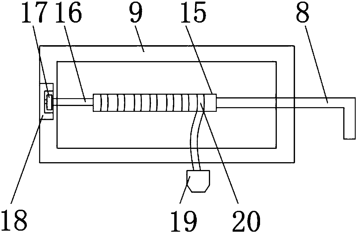
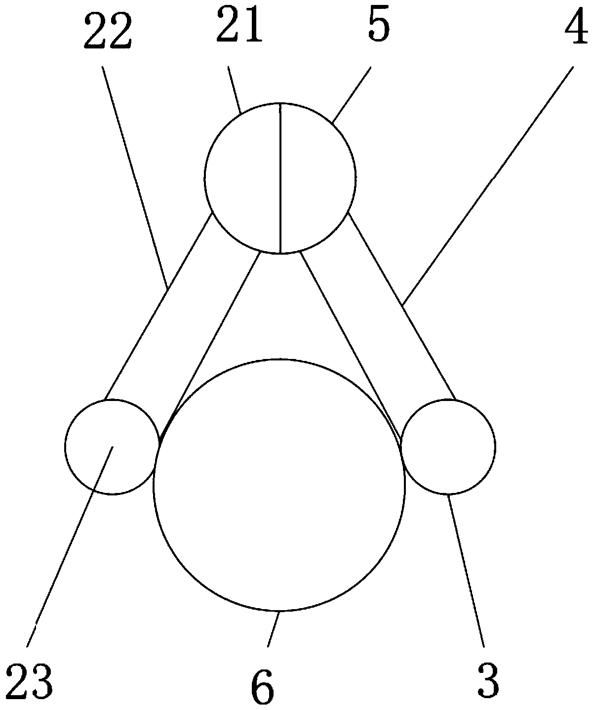
[0024] See Figure 1-6 , The present invention provides a technical solution: an electric pedal sewing machine, including a base 10, one side of the outer surface of the base 10 is fixedly installed with a wire take-up box 9, and one side of the inner surface of the wire take-up box 9 is fixedly installed with a reel The table 18 is movably installed with a rotating wheel 17 around the inside of the rotating table 18, and a connecting ro...


PUM


Abstract

The invention discloses an electric pedal sewing machine. The electric pedal sewing machine comprises a base, wherein a take-up box is fixedly installed on the outer surface of one side of the base, and a rotating platform is fixedly mounted on the inner surface of one side of the take-up box; a rotating wheel is movably mounted in the rotating platform; a connecting rod is fixedly mounted on theouter surface of one side of the rotating wheel; the outer surface of one end of the connecting rod is fixedly provided with a take-up rod; the outer surface of one side of the take-up rod is fixedlyprovided with a rotating handle; and the middle of the outer surface of the take-up rod is wound with an electric wire, and the outer surface of one end of the electric wire is fixedly connected witha plug. Through the arrangement of the take-up rod, the electric wire can be reasonably stored, so that the electric wire is prevented from being subjected to unnecessary abrasion; through a first combined plate, the first combined plate and a second combined plate can be combined together to form a grip, and a device can be carried conveniently; and by means of a limiting plate, so that stitchesare distributed more evenly and orderly on cloth.

Description

Technical field [0001] The invention relates to the technical field of garment sewing, in particular to an electric pedal sewing machine. Background technique [0002] The sewing machine is a common machine for sewing clothes and fabrics. With the development of technology, the traditional manual foot-operated sewing machine is gradually replaced by the electric sewing machine. The electric sewing machine is more convenient and labor-saving than the traditional foot-operated sewing machine. Accurate, it can also speed up the sewing speed and improve the production efficiency. The existing electric pedal sewing machine has been relatively complete in terms of structure and function, but there is still room for improvement in the use process. First of all, the fabric needs to be in the sewing process. The sewing needle is moving gradually, but the existing electric sewing machine cannot guarantee that the fabric will not deviate from the moving track when the cloth is moving, resul...

Claims


Application Information

Patent Timeline
IPC IPC(8): D05B73/02D05B73/12D05B33/00
CPCD05B33/00D05B73/02D05B73/12
Inventor 潘兴文
Owner 广西万盛服装服饰有限公司
Why Eureka
Try Eureka