High-efficiency ultrasonic cleaning device and method

An ultrasonic cleaning and high-efficiency technology, applied in cleaning methods and utensils, cleaning methods using liquids, chemical instruments and methods, etc., can solve the problems of low efficiency, poor cleaning effect, low utilization rate of sound energy, etc. Enhance the strength, enhance the effect, improve the efficiency of the effect

Pending Publication Date: 2020-03-24
HARBIN INST OF TECH
View PDF6 Cites 0 Cited by
  • Summary
  • Abstract
  • Description
  • Claims
  • Application Information

AI Technical Summary

Problems solved by technology

[0004] In order to solve the problems of poor cleaning effect, low efficiency and low utilization rate of sound energy in most existing ultrasonic cleaners, the present invention further proposes a high-efficiency ultrasonic cleaning device and method

Method used


Image

  • High-efficiency ultrasonic cleaning device and method
  • High-efficiency ultrasonic cleaning device and method
  • High-efficiency ultrasonic cleaning device and method

Examples


specific Embodiment approach 1

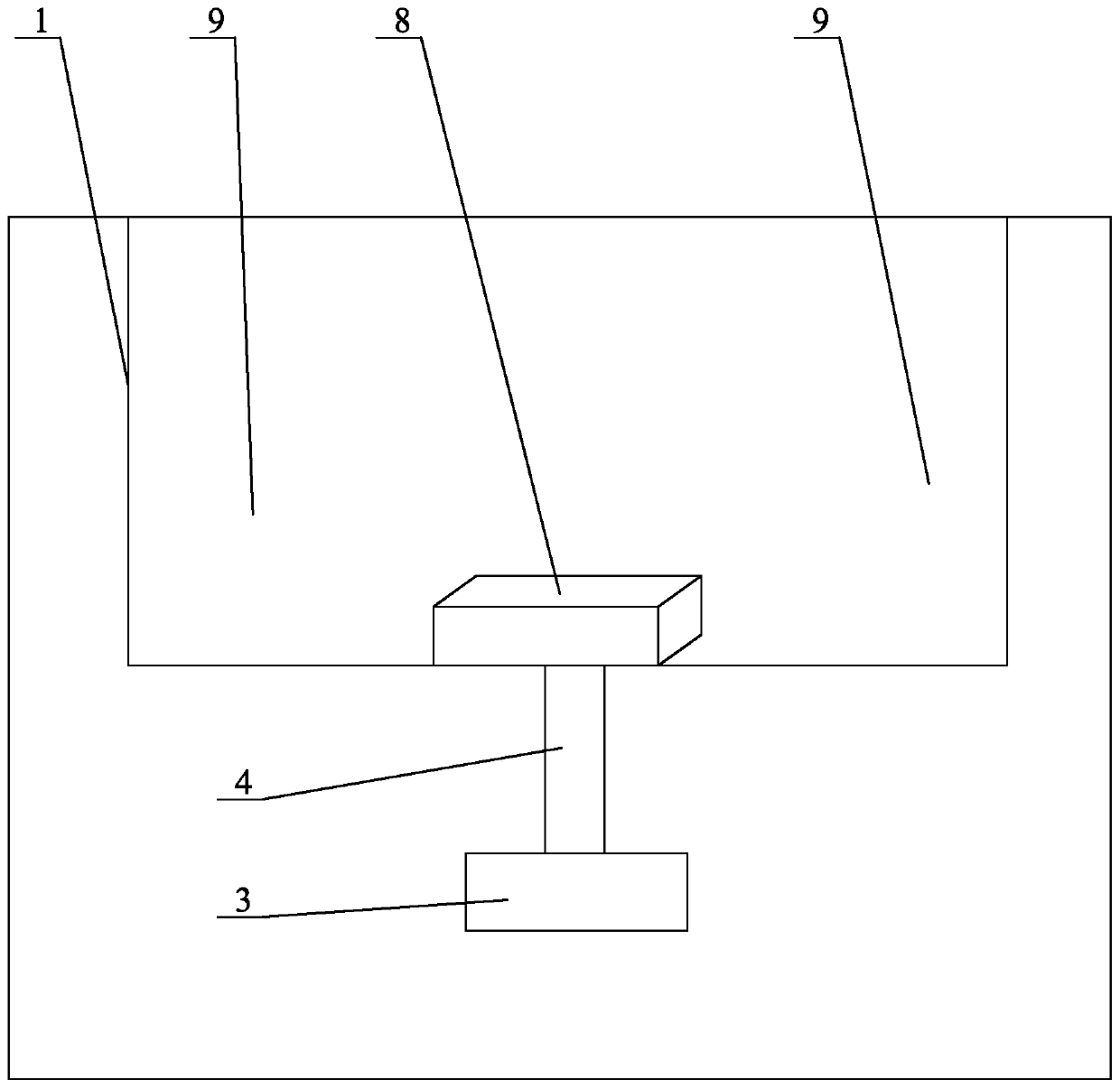
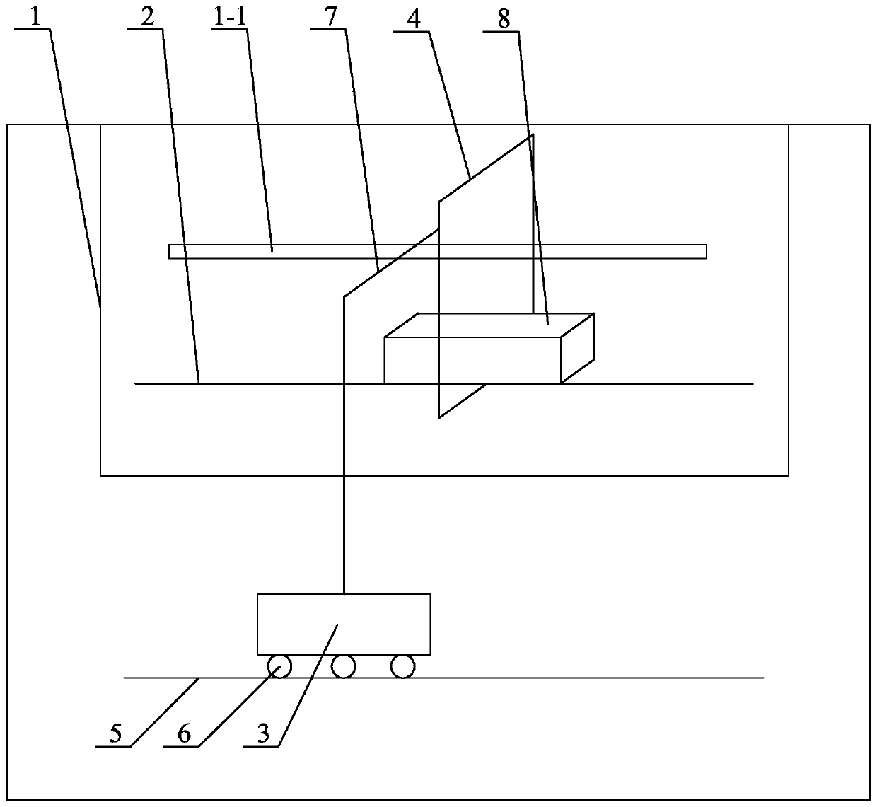
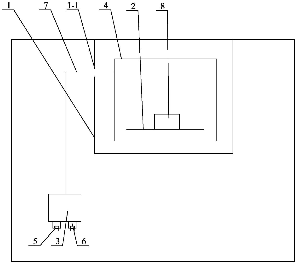
[0018] Specific implementation mode one: combine Figure 1 to Figure 4 Describe this embodiment, a high-efficiency ultrasonic cleaning device described in this embodiment includes a cleaning tank 1, a sample placement table 2, an ultrasonic generator 3, an ultrasonic head 4 and a set of slide rails 5, and the sample placement table 2 is set in the cleaning tank 1, the ultrasonic generator 3 is arranged on the outside of the cleaning tank 1, the output end of the ultrasonic generator 3 is connected to the ultrasonic head 4, the shape of the ultrasonic head 4 is a frame, the ultrasonic head 4 is arranged in the cleaning tank 1 and is set in the sample Place the outside of platform 2, the bottom of sonotrode 3 is provided with a group of slide rails 5 along the length direction, and the lower end surface of sonotrode 3 is provided with a group of rollers 6, and rollers 6 and slide rail 5 are slidingly connected.

[0019] The invention proposes a method and device that can enhance...

specific Embodiment approach 2

[0023] Specific implementation mode two: combination Figure 2 to Figure 4 To describe this embodiment, the ultrasonic head 4 in this embodiment is a square frame or a circular frame. The undisclosed technical features in this embodiment are the same as those in the first embodiment.

[0024] In this embodiment, in order to facilitate the installation of the ultrasonic head 4 on the outside of the sample placement platform 2, the sample placement platform 2 can be fixed in the cleaning tank 1 using a cantilever type, that is, one side of the lower end of the sample placement platform 2 is fixedly connected to the cleaning tank 1 , the ultrasonic head 4 is set from the other side of the sample placement platform 2; the sample placement platform 2 can also be fixed in the cleaning tank 1 in a detachable assembled manner, and one side of the lower end of the sample placement platform 2 is fixedly connected to the cleaning tank 1 , and then the ultrasonic head 4 is set from the o...

specific Embodiment approach 3

[0025] Specific implementation mode three: combination Figure 2 to Figure 4 Describe this embodiment, the sonotrode 3 described in this embodiment is arranged on the side below the cleaning tank 1, the end of the ultrasonic head 4 is connected with the output end of the sonotrode 3 through a strut 7, and the side wall of the cleaning tank 1 The upper part is provided with a through groove 1-1 along the length direction, and the pole 7 is inserted in the through groove 1-1. The undisclosed technical features in this embodiment are the same as those in the first or second specific embodiment. Such design is to prevent the ultrasonic head 4 from interfering with the cleaning tank 1 during installation. The sonotrode 3 is arranged on the side below the cleaning tank 1 to prevent the sample 8 from interfering with the sonotrode 3 and its slide rail 5 when the sample 8 is installed, making it inconvenient to place and take out the sample 8.


PUM


Abstract

The invention discloses a high-efficiency ultrasonic cleaning device and method, relates to the technical field of ultrasonic cavitation, and aims to solve the problems of poor cleaning effect, low efficiency and low sound energy utilization rate of an existing ultrasonic cleaning instrument. The cleaning device comprises a cleaning tank, a sample placing table, an ultrasonic generator, an ultrasonic head and a group of sliding rails, wherein the sample placing table is arranged in the cleaning tank, the ultrasonic generator is arranged on the outer side of the cleaning tank, the output end ofthe ultrasonic generator is connected with the ultrasonic head, the ultrasonic head is in a frame shape, the ultrasonic head is arranged in the cleaning tank and arranged on the outer side of the sample placing table in a sleeving mode, and the group of sliding rails are arranged below the ultrasonic generator in the length direction. The lower end face of the ultrasonic generator is provided with a group of rollers, and the rollers are in sliding connection with the sliding rails. The cleaning method comprises the following steps: selecting the ultrasonic generator; assembling the ultrasonicgenerator; adding a cleaning solution; and performing ultrasonic cleaning. The high-efficiency ultrasonic cleaning device and method are used for ultrasonic cleaning.

Description

technical field [0001] The invention relates to the technical field of ultrasonic cavitation, in particular to a high-efficiency ultrasonic cleaning device and method. Background technique [0002] Ultrasonic cavitation effect means that the tiny bubbles in the liquid undergo a series of processes such as nucleation, growth, oscillation and collapse under the action of the stretching of the sparse phase of the sound wave and the compression of the compression phase under the action of ultrasonic waves. The collapse time of the cavitation bubble is very short (only a few nanoseconds to a few microseconds), and it can instantly generate thousands of degrees of high temperature, several GPa of high pressure, high-speed liquid microjet and shock wave, thereby triggering many mechanical and physical phenomena. , chemical, biological and other effects, such as material destruction, accelerated chemical reaction speed, etc. The more common ultrasonic device in the laboratory is th...

Claims


Application Information

Patent Timeline
IPC IPC(8): B08B3/12
CPCB08B3/12
Inventor 李政玮陈姝许志武闫久春
Owner HARBIN INST OF TECH
Why Eureka
Try Eureka