Ultrasonic transducer, production method of ultrasonic transducer and ultrasonic equipment

An ultrasonic transducer and transducer technology, used in ultrasonic therapy, treatment and other directions, can solve the problems of outputting ultrasonic sound beams, difficult to array ultrasonic transducers, etc. Effect

Inactive Publication Date: 2020-07-28
SHENZHEN INST OF ADVANCED TECH CHINESE ACAD OF SCI
View PDF4 Cites 0 Cited by
  • Summary
  • Abstract
  • Description
  • Claims
  • Application Information

AI Technical Summary

Problems solved by technology

[0005] The embodiment of the present invention provides an ultrasonic transducer, a manufacturing method of the ultrasonic transducer, and an ultrasonic device, which solves the problem that it is difficult for the user to adapt the output of the array ultrasonic transducer in the prior art to the ultrasonic incidence area of ​​the head of the target object. Shaped Ultrasound Beam Problems

Method used


Image

  • Ultrasonic transducer, production method of ultrasonic transducer and ultrasonic equipment
  • Ultrasonic transducer, production method of ultrasonic transducer and ultrasonic equipment
  • Ultrasonic transducer, production method of ultrasonic transducer and ultrasonic equipment

Examples


Embodiment 1

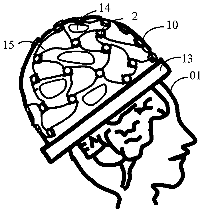
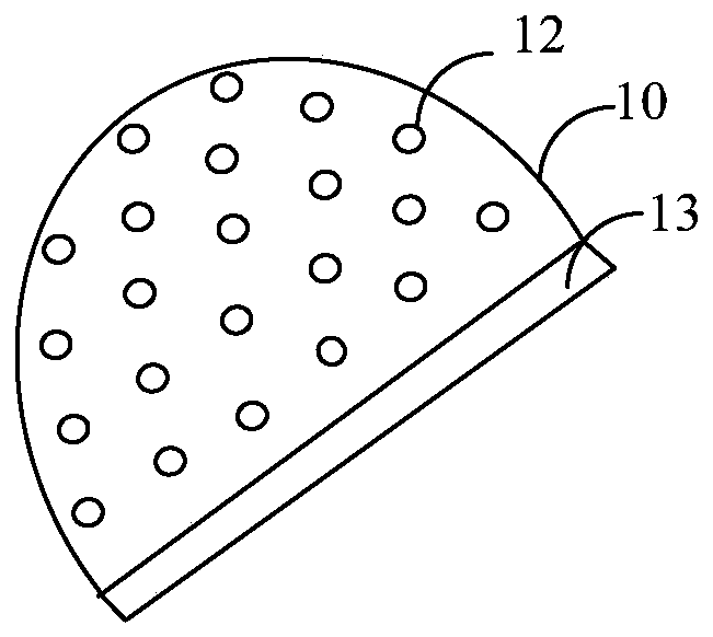
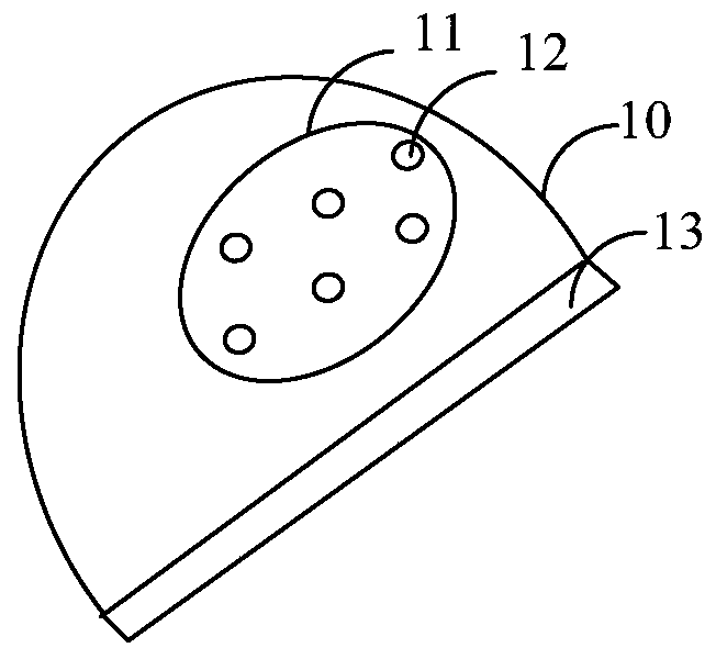
[0043] An embodiment of the present invention provides an ultrasonic transducer. like figure 1 and Figure 2A and Figure 2B As shown, the ultrasonic transducer includes a support 10 worn on the head of the target object 01 and at least two transducer array elements 2, the transducer array elements 2 are used to output ultrasound when excited; the ultrasonic output area of ​​the support It is a concave curved surface and has at least two through holes 12 for placing transducer array elements, and the orientation of each through hole 12 makes the ultrasonic sound beam formed by the ultrasound output by all transducer array elements in the ultrasonic output area and The ultrasound incidence zone of the target subject's head conforms to the shape.

[0044] Wherein, the cross section of the ultrasonic output area is preferably arc-shaped.

[0045] Wherein, the transducer array element 2 at least includes a piezoelectric layer, and the piezoelectric layer is made of piezoelectr...

Embodiment 2

[0059] Figure 7 It is a schematic diagram of the ultrasonic equipment provided by Embodiment 2 of the present invention. The ultrasonic equipment includes an excitation device 3 and the ultrasonic transducer 1 described in the foregoing embodiments, the excitation device 3 includes at least one excitation channel, and the excitation channel is connected to the corresponding transducer array element of the ultrasonic transducer 1, and is used for In order to provide excitation for the corresponding transducer array element, so that the corresponding transducer array element outputs ultrasound.

[0060] Wherein, the excitation device 3 can only comprise one excitation channel, is adapted to the transducer that comprises a transducer array element; The excitation device also can comprise a plurality of excitation channels, can directly be each transducer array element in the transducer Provide motivational support. If one excitation channel only provides excitation support for...

Embodiment 3

[0064] Figure 8 It is a flow chart of the manufacturing method of the ultrasonic transducer provided by Embodiment 3 of the present invention. This method is used to manufacture the ultrasonic transducer described in the foregoing embodiments. to combine figure 1 , Figure 2A and Figure 2B , the method includes:

[0065] S101. Determine the position and shape of the ultrasonic output area of ​​the stent according to the shape of the ultrasonic incident area and the position of the ultrasonic incident area on the head of the target subject, and the shape of the ultrasonic output area is a concave curved surface.

[0066] Ultrasound output zone 11 may occupy the entirety of the stent (see figure 1 and Figure 2A ), or possibly only part of it (see Figure 2B ). For the former, the entire head of the target subject is the ultrasound incident area, that is, the head of the target subject receives ultrasound from any direction; for the latter, only the part designated as ...


PUM

PropertyMeasurementUnit
Acute angleaaaaaaaaaa

Abstract

An embodiment of the invention discloses an ultrasonic transducer, a production method of the ultrasonic transducer and ultrasonic equipment. The ultrasonic transducer comprises at least two transducer array elements for outputting ultrasonic when excited and a support worn on the head of a target object, wherein an ultrasonic output zone of the support is an inwards concave curved surface, at least two through holes for placing the transducer array elements are formed in the inwards concave curved surface, and the direction of each through hole enables an ultrasonic beam formed by ultrasonicoutput by all transducer array elements in the ultrasonic output zone to conform to an ultrasonic incidence zone on the head of the target object. The problem that a user is difficult to output an ultrasonic beam conforming to the ultrasonic incidence zone on the head of the target object through an array ultrasonic transducer in the prior art is solved.

Description

technical field [0001] Embodiments of the present invention relate to the field of medical equipment, and in particular, to an ultrasonic transducer, a manufacturing method of the ultrasonic transducer, and ultrasonic equipment. Background technique [0002] Because ultrasound can provide safe, noninvasive, and precise nerve stimulation, transcranial ultrasound therapy is increasingly used in the treatment of neurological and psychiatric diseases, such as Parkinson's disease, epilepsy, and depression. [0003] Transcranial ultrasound therapy is a non-invasive technology, through the cavitation effect, thermal effect, mechanical effect and other effects on the target lesion, it has a direct or indirect effect on the patient's brain lesions, and has been used in acute cerebral infarction, cerebral hemorrhage and other diseases Definite curative effect has been obtained in the treatment operation. At present, single-array elements and array transducers are mainly used for ultr...

Claims


Application Information

Patent Timeline
IPC IPC(8): A61N7/00
CPCA61N7/00A61N2007/003A61N2007/0043A61N2007/0056A61N2007/0065
Inventor 邱维宝蔡蕊琳苏敏张志强郑海荣
Owner SHENZHEN INST OF ADVANCED TECH CHINESE ACAD OF SCI
Why Eureka
Try Eureka