Rope-driven flexible claw and robot

A rope-driven flexible and flexible skeleton technology, applied in the field of robotics, can solve the problems of limited robot movement, unfavorable finishing and storage, and large space occupation, so as to improve the application range and product grabbing efficiency, avoid movement restrictions, The effect of reducing the occupied space

Inactive Publication Date: 2020-03-24
HARBIN INST OF TECH SHENZHEN GRADUATE SCHOOL
View PDF7 Cites 1 Cited by
  • Summary
  • Abstract
  • Description
  • Claims
  • Application Information

AI Technical Summary

Problems solved by technology

[0003] The structure of traditional articulated robots is complex, the working space is small, and the joints are easy to interfere, resulting in limited movement of the robot, and when the robot is in an idle state, it occupies a large space, which is not conducive to organization and storage

Method used


Image

  • Rope-driven flexible claw and robot
  • Rope-driven flexible claw and robot
  • Rope-driven flexible claw and robot

Examples


no. 1 example

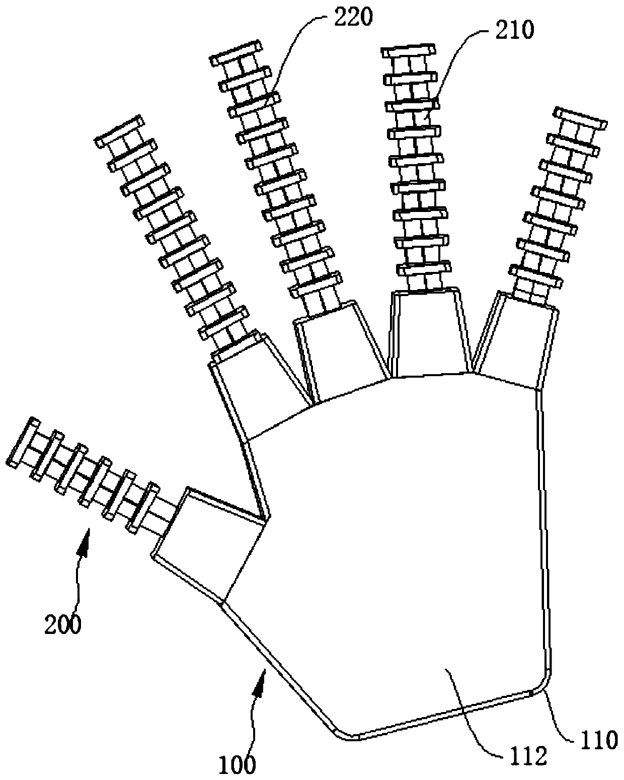
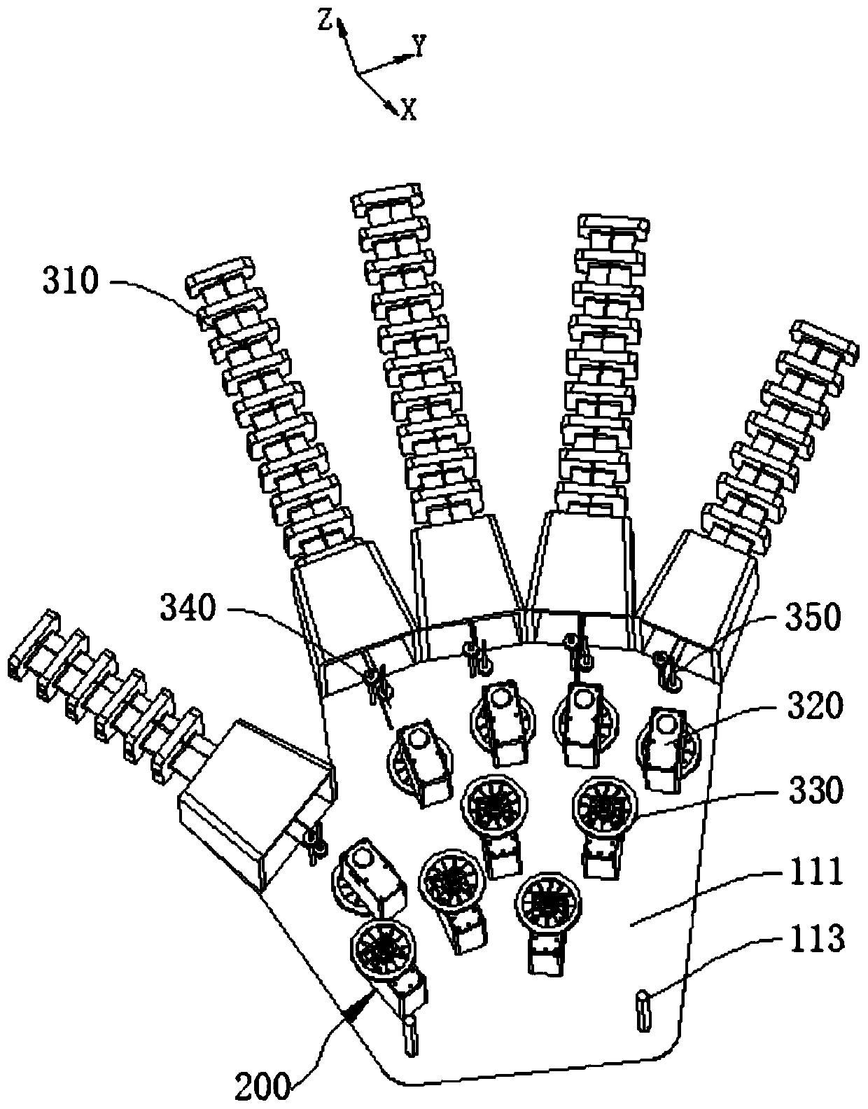
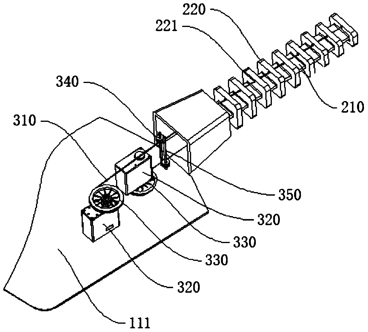
[0032] figure 1 is a schematic diagram of the overall structure of the rope-driven flexible claw, figure 2 It is a schematic diagram of the structure of the flexible claw of the rope drive after hiding part of the housing 110, image 3 is the structural diagram of the drive unit, and refer to Figure 1 to Figure 3 , the rope-driven flexible claw in this embodiment includes a fixed part 100, a finger part 200 and a driving part 300, the fixing part 100 includes a housing 110, the housing 110 provides an installation space for the driving part 300, and the driving part 300 is the finger part 200. Bending provides power support; specifically, there are no less than two fingers 200 and are installed on the edge of the fixed part 100, the fingers 200 include a flexible skeleton 210 and a plurality of joint units 220, and the joint units 220 are arranged at intervals on the flexible skeleton 210 , the section of the joint unit 220 gradually decreases along the direction away from...

no. 2 example

[0045] refer to Figure 5 The difference between this embodiment and the first embodiment is that the flexible skeleton 210 in this embodiment adopts a variable cross-section configuration, the cross section of the flexible skeleton 210 gradually decreases along the direction away from the fixed part 100, and the joint unit 220 adopts a constant cross-section structure. type, the cross-sectional shapes of different joint units 220 are the same. Therefore, when the driving rope 310 is pulled or released, the driving force required for bending the finger 200 is relatively small, and under the condition that the driving force applied by the driving part 300 is the same, the finger 200 in this embodiment has better load capacity.

no. 3 example

[0047] refer to Image 6 , this embodiment combines the features of the finger portion 200 in the first embodiment and the second embodiment, that is, both the flexible skeleton 210 and the joint unit 220 adopt a variable cross-section configuration, and the cross-sections of the flexible skeleton 210 and the joint unit 220 are along the back. The direction of the fixed portion 100 gradually decreases, thereby improving the load capacity of the finger portion 200 on the premise of overcoming the limitation of the movement of the finger portion 200 and reducing the space required for placing the flexible claw.

[0048] The present invention also provides a robot, which includes the above-mentioned rope-driven flexible gripper, uses the above-mentioned rope-driven flexible gripper to cooperatively grasp objects, and is applicable to product grasping in different situations.


PUM


Abstract

The invention discloses a rope-driven flexible claw and a robot. The rope-driven flexible claw comprises a fixation part, finger parts and driving parts. The number of the finger parts is not less than two; each finger part comprises a flexible framework and a plurality of joint units; the joint units are arranged at intervals along the flexible framework; the sections of the joint units are gradually reduced in the direction deviating from the fixation part; each finger part is connected with the driving part; the driving part comprises a driving rope and a driving element; one end of the driving rope of each driving part sequentially penetrates through each joint unit in the finger part connected with the driving part, and the other end of the driving rope is connected with the driving element and is driven by the driving element to move so as to drive the finger part to bend; and the robot comprises the rope-driven flexible claw. Variable cross-section treatment is conducted on thejoint units, so that the finger parts have enough movement space, and movement limitation is avoided; and the finger parts can be curled up, so that the space occupied by the flexible claw is reduced;and the tail ends of the finger parts move flexibly, so that the reliability of the flexible claw in the material grabbing process is improved.

Description

technical field [0001] The invention relates to the technical field of robots, in particular to a rope-driven flexible claw and a robot. Background technique [0002] In order to reduce labor costs and overcome the harsh operating environment, the demand for robots in the existing market is gradually increasing. Robots have been gradually used in various fields such as medical treatment, military, and industry. The joint-type gripper is installed on the robot because of its high flexibility. In order to achieve a variety of grabbing tasks. [0003] The structure of traditional articulated robots is complex, the working space is small, and the joints are easy to interfere with each other, resulting in limited movement of the robot, and when the robot is in an idle state, it occupies a large space, which is not conducive to organization and storage. Contents of the invention [0004] The present invention aims to solve at least one of the technical problems existing in the ...

Claims


Application Information

Patent Timeline
IPC IPC(8): B25J15/12
CPCB25J15/12
Inventor 袁晗李钻徐文福
Owner HARBIN INST OF TECH SHENZHEN GRADUATE SCHOOL
Why Eureka
Try Eureka