[0027] The technical solutions in the embodiments of the present invention will be clearly and completely described below in conjunction with the accompanying drawings in the embodiments of the present invention. Obviously, the described embodiments are only a part of the embodiments of the present invention, rather than all the embodiments. Based on the embodiments of the present invention, all other embodiments obtained by those of ordinary skill in the art without creative work shall fall within the protection scope of the present invention.
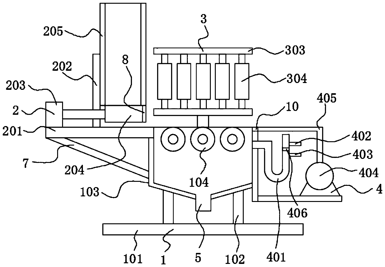
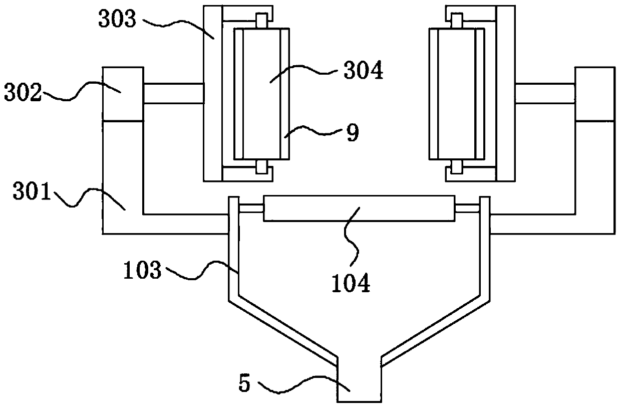
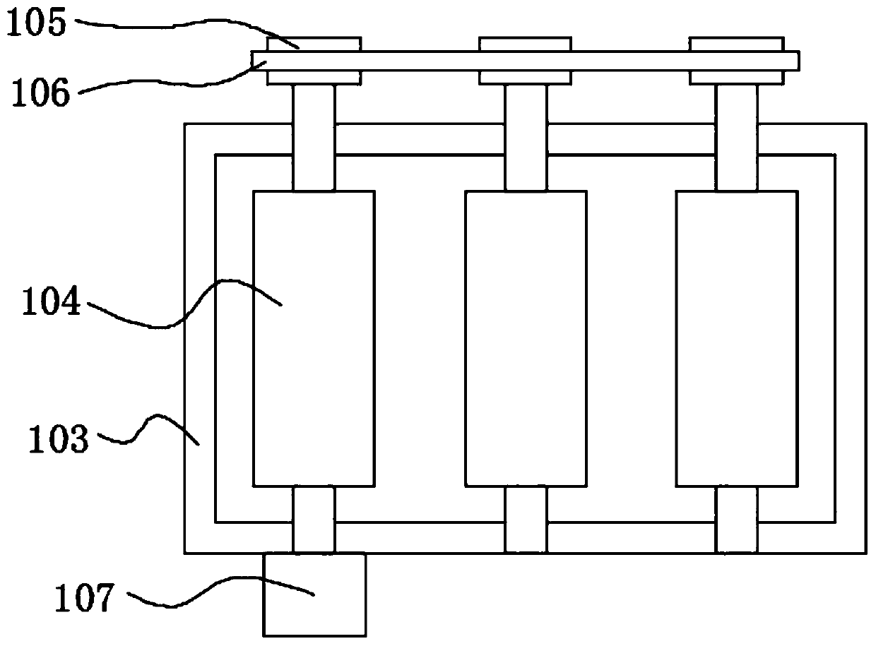
[0028] See Figure 1-3 , The present invention provides a technical solution: a feeding and pushing mechanism for an ink cartridge packaging machine, comprising: a glue application assembly 1, the glue application assembly 1 includes a support base 101, a frame 102, a glue storage box 103 and a number of glue rollers 104 , The frame body 102 is installed on the upper part of the support base 101, the glue storage box 103 is installed on the upper part of the frame body 102, and a plurality of glue rollers 104 are mounted on the two side walls of the glue storage box 103 through a bearing rotation. The roller shafts are equipped with gears 105, and several gears 105 are driven by chains 106. The side of the glue storage box 103 is equipped with a geared motor 107 through a motor seat. The geared motor 107 is connected to the roller shafts of a set of glue rollers 104. The lower part of the glue box 103 is arranged in a funnel shape. The lower part of the glue storage box 103 is connected with a glue discharge pipe 5. The side of the glue storage box 103 is installed with a protective cover 6 through bolts. The protective cover 6 covers the outside of the gear 105 and the chain 106. The upper walls of the plurality of glue rollers 104 and the upper wall of the carrier board 201 are all on the same horizontal plane, and the gap between the plurality of glue rollers 104 is 2cm-3cm;
[0029] The material pushing assembly 2 includes a carrying plate 201, a supporting frame 202, a first electric push rod 203, a sliding block 204 and an ink cartridge placement tube 205. The carrying plate 201 is installed on the side of the glue storage box 103, and the first electric The push rod 203 is installed on the upper part of the carrier plate 201, the sliding block 204 is installed on the output end of the first electric push rod 203 through bolts, the support frame 202 is installed on the upper part of the carrier plate 201 through bolts, and the ink cartridge placement tube 205 is installed on the support through bolts. Between the shelves 202, the upper part of the sliding block 204 slides against the lower part of the ink cartridge placing tube 205. The upper wall of the carrying plate 201, the outer wall of the sliding block 204 and the inner wall of the ink cartridge placing tube 205 are all smooth surfaces. The side part is threadedly connected with the side part of the glue storage box 103 with the diagonal brace 7, the sliding block 204 is arranged in a strip shape, the lower wall of the sliding block 204 and the upper wall of the carrying board 201 are in clearance fit, and the end of the sliding block 204 is glued Connected with silicone pad 8;
[0030] The limit component 3, the limit component 3 includes two sets of support blocks 301, two sets of second electric push rods 302, two sets of connecting frames 303 and a number of guide rollers 304. The two sets of support blocks 301 are installed on the side of the glue storage box 103 , The two sets of second electric push rods 302 are installed on the upper part of the two sets of support blocks 301, the two sets of connecting frames 303 are all installed on the output ends of the two sets of second electric push rods 302 by bolts, and a number of guide rollers 304 are all rotated through bearings Installed on the sides of two sets of connecting frames 303, the lower part of the two sets of connecting frames 303 is in clearance fit with the upper wall of the glue storage box 103, the two sets of connecting frames 303 are arranged oppositely, and the side sections of the two sets of connecting frames 303 are It is arranged in a concave shape, and the outer sides of several guide rollers 304 are glued with a rubber sleeve 9, and the outer wall of the rubber sleeve 9 is a smooth surface;
[0031] And the glue replenishment component 4, which includes a connector 401, a first photoelectric switch 402, a second photoelectric switch 403, a replenishing pump 404, and a refill tube 405. The connector 401 is installed on the side of the glue storage box 103 and communicates with The side section of the connector 401 is U-shaped, a sealing ring 10 is arranged between the liquid inlet end of the connector 401 and the glue storage tank 103, and the first photoelectric switch 402 and the second photoelectric switch 403 are both installed on the side of the connector 401 A float 406 is installed inside the connector 401. The detection end of the first photoelectric switch 402 and the detection end of the second photoelectric switch 403 are opposite to the side of the connector 401. The first photoelectric switch 402 and the second photoelectric switch 403 Both are electrically connected to the glue filling pump 404, and the glue outlet end of the glue filling pump 404 is in communication with the side of the glue storage tank 103 through the glue filling pipe 405.
[0032] Working principle: by injecting glue into the glue storage box 103, the glue will flood the lower part of the glue roller 104, by stacking the ink cartridges inside the ink cartridge placing tube 205, and pushing the sliding block 204 to move through the first electric push rod 203, Push the ink cartridge to the upper part of the rubber roller 104, and in the process of pushing the material, use the upper part of the sliding block 204 to block the lower part of the ink cartridge placing tube 205 to prevent other ink cartridges from falling onto the upper part of the carrier plate 201 and pass the first The telescopic and elongation of an electric push rod 203 realizes a fast pushing process, avoids manual feeding, and is convenient to use;
[0033] The operation of the decelerating motor 107 drives a group of glue rollers 104 to rotate, and the cooperation of the chain 106 and the gear 105 drives all the glue rollers 104 to rotate, and then drives the ink cartridge on the upper part of the glue roller 104 to move. The movement is constantly in contact with the glue inside the glue storage box 103, and during the movement of the glue roller 104, the glue is smeared on the lower part of the ink cartridge to realize the glue application process, avoiding the glue first and then moving, which is completed during the movement The glue application process avoids the glue dripping;
[0034] Through the operation of the two sets of second electric push rods 302, the two sets of connecting frames 303 are moved closer or farther away, and the ink cartridges moving from the upper part of the glue roller 104 are restricted to prevent the ink cartridges from falling from both sides of the glue storage box 103;
[0035] The glue storage tank 103 is connected through the communicating device 401, so that the glue height inside the glue storage box 103 is consistent with the glue height in the communicating device 401. As the glue application process progresses, the float 406 is continuously lowered and the second photoelectric switch 403 of Bing and The detection end of the second photoelectric switch 403 is triggered to act, and then the glue filling pump 404 is turned on to make glue. As the glue filling progresses, the float 406 rises and opposes the detection end of the first photoelectric switch 402 to trigger the first photoelectric switch 402. The switch 402 is activated to stop the glue filling pump 404, which effectively realizes the glue filling process, so that the glue roller 104 is always in contact with the glue.
[0036] Although the embodiments of the present invention have been shown and described, those of ordinary skill in the art can understand that various changes, modifications, and substitutions can be made to these embodiments without departing from the principle and spirit of the present invention. And variations, the scope of the present invention is defined by the appended claims and their equivalents.