
Tail jet flow direction test section length selection method for infrared radiation test

An infrared radiation and tail jet technology, applied in the field of infrared spectral radiation testing, can solve the problems of reduced signal-to-noise ratio, attenuation of infrared radiation signals, and increased proportion of background radiation.

Active Publication Date: 2020-03-24
AIR FORCE UNIV PLA
View PDF4 Cites 0 Cited by
  • Summary
  • Abstract
  • Description
  • Claims
  • Application Information

AI Technical Summary

Problems solved by technology

The gas infrared radiation intensity of the engine tail jet is much smaller than the solid infrared radiation intensity of the engine inner wall and the central cone. In addition, the Fourier transform infrared spectrometer is placed far away, and the infrared radiation signal is seriously attenuated after being transmitted through the long-distance atmosphere. The signal received by the infrared spectrometer is greatly weakened, and the proportion of background radiation increases, resulting in a decrease in the signal-to-noise ratio, and there are large errors in the measurement results

Method used


Image

  • Tail jet flow direction test section length selection method for infrared radiation test
  • Tail jet flow direction test section length selection method for infrared radiation test
  • Tail jet flow direction test section length selection method for infrared radiation test

Examples


Embodiment Construction

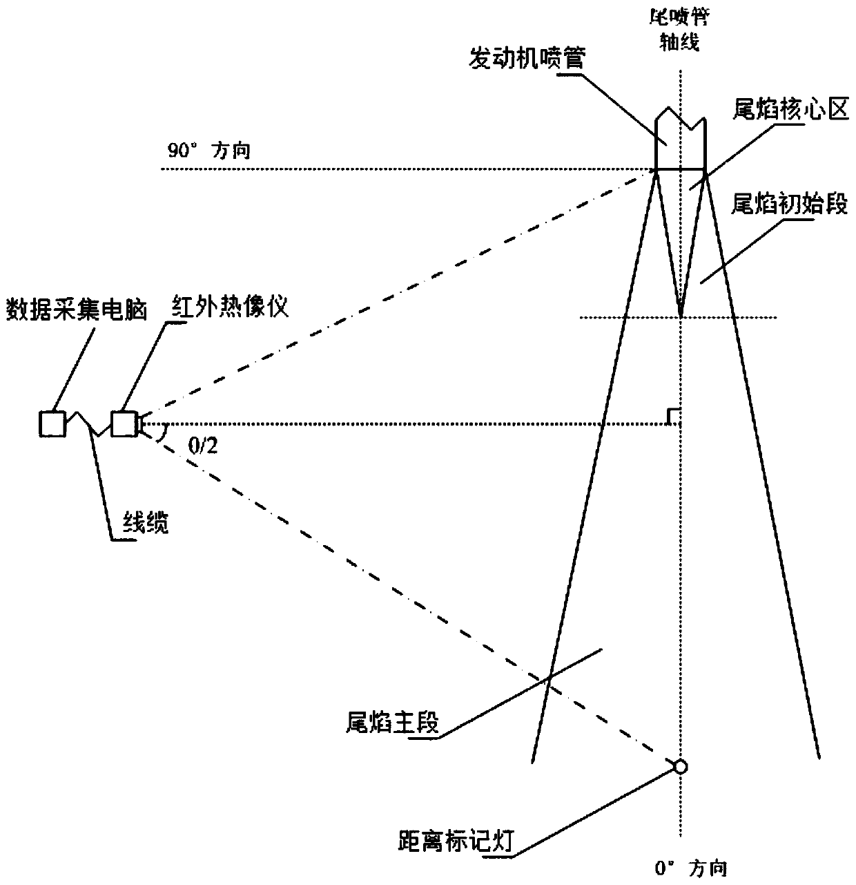
[0042] Such as Figure 1-3 As shown, this embodiment chooses to carry out at night when the wind force level is less than 1, and uses the SC7300M type mid-wave infrared thermal imager to test the engine tail jet flow. When equipped with a 12 mm lens, the field of view of this type of infrared thermal imager is 44°×36°, that is, the horizontal field of view is 44°, the vertical field of view is 36°, and the pixel size is 320×256; a method for selecting the length of the tail jet flow direction test section for infrared radiation testing, and the specific steps of the method as follows:

[0043]Step 1): Set the 30m distance marking light and the marking point at the preset distance. The preset distance of the marking point can be set and modified according to actual needs. Here, the marking point of 15m is used; the laser of the laser collimator is emitted Set the laser collimator at one end of the engine exhaust pipe, and make the emitted laser parallel to the axis of the engi...


PUM


Abstract

The invention discloses a tail jet flow direction test section length selection method for an infrared radiation test, and the method comprises the following steps: firstly, setting a 30m distance marking lamp and a 15m marking point; secondly, arranging a medium-wave thermal infrared imager; then, an engine being subjected to test run, and using a medium-wave thermal infrared imager for shootingan infrared thermogram of the tail jet flow; performing test run according to the test run process, measuring the tail jet flow by using a medium-wave thermal infrared imager to obtain infrared thermograms of various states after the state of the engine is stabilized for preset time when the engine is in a typical working state, and closing the medium-wave thermal infrared imager and disconnectinga cable after the test run of the engine is finished; thirdly, processing the infrared thermogram obtained in the third step to obtain a tail jet flow infrared radiation field. The method is used forassisting in determining the measurement distance of the Fourier infrared spectrometer, and the requirement that the Fourier infrared spectrometer is used for carrying out infrared spectrum radiationcharacteristic testing on the aero-engine in an external field is met.

Description

technical field [0001] The invention belongs to the field of infrared spectral radiation testing, in particular to a method for selecting the length of a tail jet flow direction test section for infrared radiation testing. Background technique [0002] The aeroengine is an important source of infrared radiation in the tail direction of the aircraft. Measuring its infrared spectral radiation characteristics can provide an important reference for the stealth design of the engine and the evaluation of stealth performance. At present, Fourier transform infrared spectrometers are mostly used for testing the infrared spectral radiation characteristics of the engine tail direction. The Fourier transform infrared spectrometer has the advantages of multi-channel simultaneous measurement, high precision, and high signal-to-noise ratio. However, in the process of testing the infrared spectral radiation characteristics of aeroengines, the field of view is small, and the signal-to-noise ...

Claims


Application Information

Patent Timeline
Patent Type & Authority Applications(China)
IPC IPC(8): G01M15/14G01N21/3504
CPCG01M15/14G01N21/3504
Inventor 李益文匡鹏陈戈王超哲魏小龙李玉琴李军化为卓
Owner AIR FORCE UNIV PLA
Learn More