Simple calculation method for maximum principal stress of underground diaphragm wall in excavation stage

A technology of maximum principal stress and calculation method, which is applied in design optimization/simulation, instrumentation, geometric CAD, etc., can solve the cumbersome calculation of maximum principal stress and other problems, and achieve the effects of high precision, simple calculation and simplified calculation

Inactive Publication Date: 2020-03-24
广西荔玉高速公路有限公司 +1
View PDF0 Cites 0 Cited by
  • Summary
  • Abstract
  • Description
  • Claims
  • Application Information

AI Technical Summary

Problems solved by technology

[0003] The purpose of the present invention is to solve the above-mentioned existing problems, provide a simple calculation method for the maximum principal stress of the ground connection wall in the excavation stage, obtain the maximum principal stress formula of the ground connection wall under different excavation depths, and use this formula for During the excavation process of the ground connection wall in the project construction, the formula has the characteristics of simple calculation and high precision, which can fully meet the construction monitoring requirements, and solves the problem of cumbersome calculation of the maximum principal stress during the excavation process of the ground connection wall in the project construction

Method used


Image

  • Simple calculation method for maximum principal stress of underground diaphragm wall in excavation stage
  • Simple calculation method for maximum principal stress of underground diaphragm wall in excavation stage
  • Simple calculation method for maximum principal stress of underground diaphragm wall in excavation stage

Examples


Embodiment

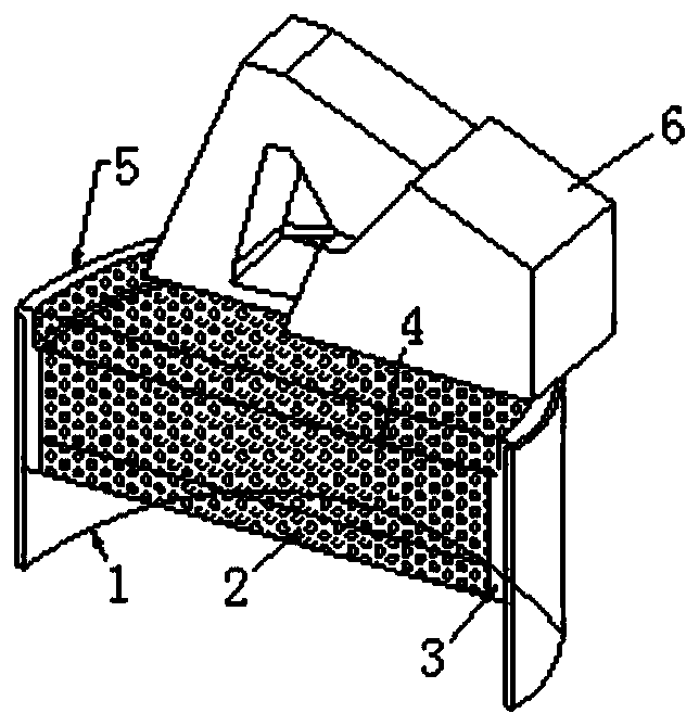
[0047] Such as Figure 1-2 As shown, a simple calculation method for the maximum principal stress of the ground connection wall in the excavation stage includes the following steps:

[0048] Step S1: Establish the finite element model of the ground connection wall excavation stage, the model is a groove body, the finite element model includes the ground connection wall 1, the bottom plate 2, the lining 3 and the filling core 4, the ground connection wall 1 is a semi-cylindrical body, The bottom of the finite element model is provided with a bottom plate 2, the inner side of the ground connection wall 1 is provided with a lining 3, the finite element model is filled with a filler core 4, and an abutment 6 is provided above the finite element model, and the ground connection wall 1 The top is the cap beam 5.

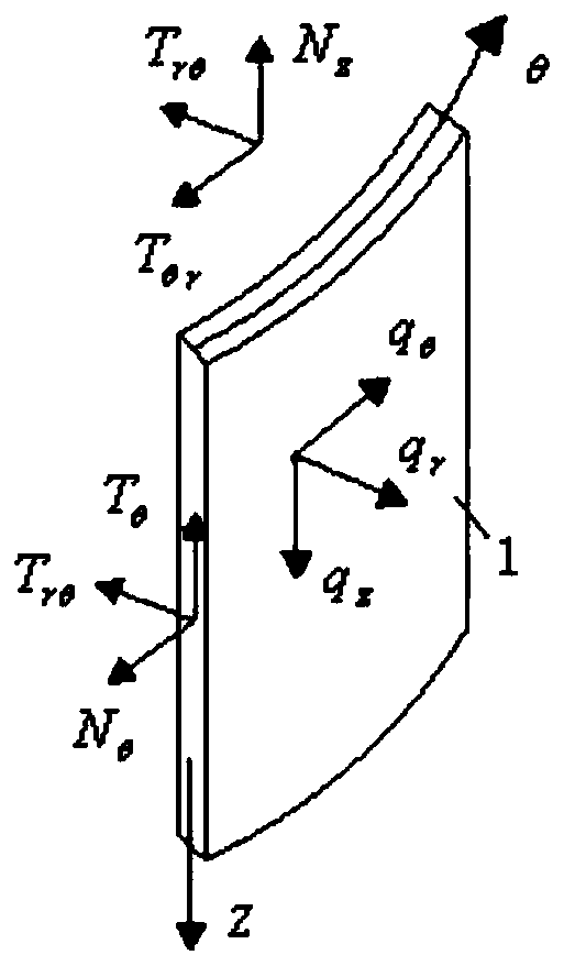
[0049] Step S2: Simplify the ground connection wall 1 into a cylindrical surface, select a cylindrical surface on the ground connection wall 1 and establish a surface coord...


PUM

PropertyMeasurementUnit
Total heightaaaaaaaaaa
Lengthaaaaaaaaaa
Lengthaaaaaaaaaa

Abstract

The invention relates to the technical field of calculation of main stress of an underground diaphragm wall, and particularly relates to a simple calculation method for the maximum principal stress ofan underground diaphragm wall in an excavation stage. The method comprises the following steps: S1, establishing a model of the diaphragm wall excavation stage, wherein the model comprises a diaphragm wall, a bottom plate, a lining and a filling core, the diaphragm wall is a semicircular cylinder, the bottom plate is arranged at the bottom of the model, the lining is tightly attached to the innerside of the diaphragm wall, and the model is filled with the filling core; s2, simplifying the diaphragm wall into a cylindrical curved surface, selecting one cylindrical curved surface on the diaphragm wall, and establishing a curved surface coordinate system on the cylindrical curved surface; and S3, solving a calculation formula of the maximum principal stress of the underground diaphragm wall. According to the method, the maximum principal stress formula of the diaphragm wall under different excavation depths is obtained, the formula is used in the excavation process of the diaphragm wallin project construction, and the result shows that the formula has the advantages of being easy and convenient to calculate, high in precision and the like and can completely meet the construction monitoring requirement.

Description

【Technical field】 [0001] The invention relates to the technical field of calculating the principal stress of a ground connection wall, in particular to a simple calculation method for the maximum principal stress of a ground connection wall during an excavation stage. 【Background technique】 [0002] In the construction of large-scale foundations, the construction method of using ground connection walls as supporting structures is becoming more and more widespread. The ground connection wall can not only be used as a retaining and anti-seepage structure during the excavation stage, but also a permanent barrier for the foundation. In order to ensure that the ground connection wall can complete its specific function, it is necessary to ensure its safety. Especially in the foundation excavation process, ensuring that it does not crack will have far-reaching significance for the construction and even operation stages. The physical parameter directly related to cracking is the m...

Claims


Application Information

Patent Timeline
IPC IPC(8): G06F30/13G06F30/23G06F119/14
Inventor 谢来坤吴进星李玉彬刘世建王龙林郝天之王华彭曦
Owner 广西荔玉高速公路有限公司
Why Eureka
Try Eureka