Combined connector accessory and application
A combined connector and connector technology, which is applied to the parts, connections, electrical components, etc. of the connection device, can solve the problems of increasing the type and quantity of inventory parts, management costs, and affecting accuracy, so as to reduce the risk of changes , The effect of reducing the number of spare parts
- Summary
- Abstract
- Description
- Claims
- Application Information
AI Technical Summary
Problems solved by technology
Method used
Image

Examples
Embodiment 1
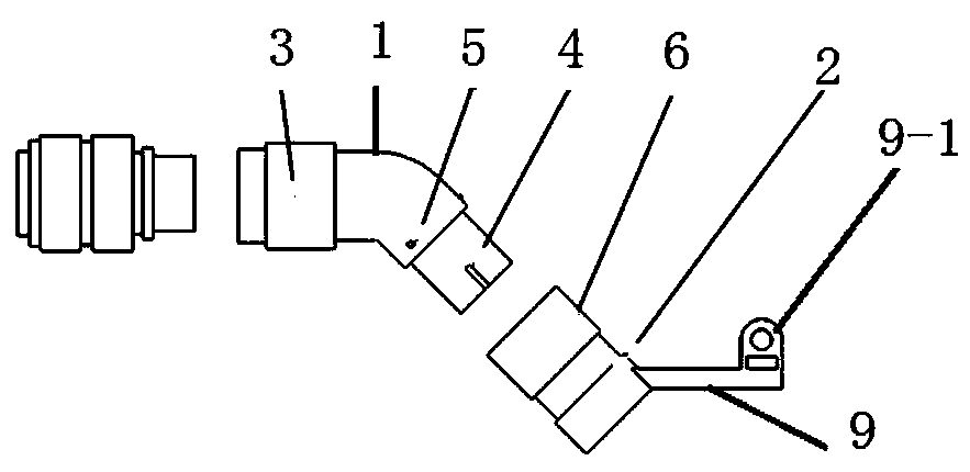
[0025] Straight-line outlet method: 1) When installing the wire harness, first insert the wire harness into the first-level component 1 and the second-level component 2; 2) For the installation of the connector component, first connect the first-level component 1 to the connector 10, and then Outlet installation angle, adjust the single arm structure 9 to be parallel to the horizontal plane, and connect the installation key protrusion 7 of the secondary component 2 with the key groove of the primary component 1 according to the installation angle; 3) Tighten the secondary component 2 The quick-release mounting ring 6 on the top is used to install the secondary component 2 on the primary component 1, and bind and fix the wire harness.
Embodiment 2
[0027] 45° wire outlet method: 1) When installing the wire harness, first insert the wire harness into the first-level component 1 and the second-level component 2; 2) For the installation of the connector component, first connect the first-level component 1 to the connector 10, and then For the installation angle of the outgoing line, adjust the single arm structure 9 to an angle of 45° with the axis of the pipeline, and connect the installation key protrusion 7 of the secondary component 2 with the key groove of the primary component 1 according to the installation angle; 3 ) Tighten the quick-release mounting ring 6 on the secondary assembly 2, install the secondary assembly 2 on the primary assembly 1, and bind and fix the wire harness.
Embodiment 3
[0029] 90° wire outlet method: 1) When installing the wire harness, first insert the wire harness into the first-level component 1 and the second-level component 2; 2) For the installation of the connector component, first connect the first-level component 1 to the connector 10, and then For the installation angle of the outgoing line, adjust the single arm structure 9 to an angle of 90° with the axis of the pipeline, and connect the installation key protrusion 7 of the secondary component 2 with the key groove of the primary component 1 according to the installation angle; 3 ) Tighten the quick-release mounting ring 6 on the secondary assembly 2, install the secondary assembly 2 on the primary assembly 1, and bind and fix the wire harness.
PUM
 Abstract
Description
Claims
Application Information