Shielding case with storable mounting position

A technology of shielding cover and installation position, applied in the field of shielding cover, which can solve the problems of contact damage on the upper part of the shielding cover shell, heat dissipation of the shielding cover, poor shock absorption effect, and reduced reliability of devices, so as to improve the heat dissipation function and heat dissipation effect Good, good shock absorption effect

Active Publication Date: 2020-03-24
扬州鑫龙电器有限公司
View PDF3 Cites 0 Cited by
  • Summary
  • Abstract
  • Description
  • Claims
  • Application Information

AI Technical Summary

Problems solved by technology

[0002] With the continuous improvement of living standards, people's daily requirements are also increasing, especially for automation control, so electronic devices have become particularly important, but because electronic devices themselves are susceptible to external interference and static electricity, they need Add protective shields to electronic components, but the existing shields on the market are generally stretched, curled, and stamped as a whole. They have no storage function, are not easy to store, and take up a lot of space. , The shock absorption effect is poor, the device may be damaged when it is in contact with the upper part of the shielding case when it is shaken, the heat generated by the device is not easy to dissipate, the components are easily damaged, and the reliability of the device is greatly reduced. The cover is no longer suitable for continued promotion and use

Method used


Image

  • Shielding case with storable mounting position
  • Shielding case with storable mounting position
  • Shielding case with storable mounting position

Examples


Embodiment 1

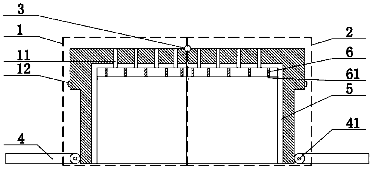
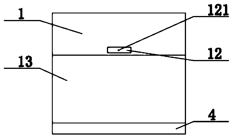
[0019] see Figure 1-Figure 3 As shown, the technical solution adopted in this specific embodiment is: it consists of the first shield split body 1, the second shield split body 2, the first hinge shaft 3, the mounting part 4, the insulating layer 5, and the cooling fins 6 The first shield split body 1 is provided with a heat dissipation through hole 11, and the heat dissipation through hole 11 is integrally formed with the first shield split body 1. The outer wall of the split body 1 is provided with a groove body 13, the groove body 13 is integrally formed with the first shield split body 1, the second shield split body 2 is hingedly installed on the right side of the first shield split body 1, and the second shield The cover split body 2 and the first shield split body 1 are hinged and fixed through the first hinge shaft 3, and the bottoms of the first shield split body 1 and the second shield split body 2 are both hinged and fixed to the installation part 4, and the instal...

Embodiment 2

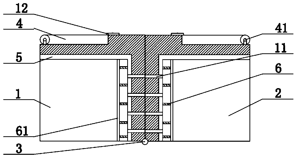
[0026] see Figure 4 As shown, the technical solution adopted in this specific embodiment is: it consists of the first shield split body 1, the second shield split body 2, the first hinge shaft 3, the mounting part 4, the insulating layer 5, and the cooling fins 6 The first shield split body 1 is provided with a heat dissipation through hole 11, and the heat dissipation through hole 11 is integrally formed with the first shield split body 1. The outer wall of the split body 1 is provided with a groove body 13, the groove body 13 is integrally formed with the first shield split body 1, the second shield split body 2 is hingedly installed on the right side of the first shield split body 1, and the second shield The cover split body 2 and the first shield split body 1 are hinged and fixed through the first hinge shaft 3, and the bottoms of the first shield split body 1 and the second shield split body 2 are both hinged and fixed to the installation part 4, and the installation pa...


PUM


Abstract

The utility model discloses a shielding case with a storable mounting position, and relates to the technical field of shielding cases. The shielding case comprises a first shielding case split body, asecond shielding case split body, a first articulated shaft, a mounting part, an insulating layer and radiating fins. Heat dissipation through holes are formed in the first shielding cover split body. A clamping block is fixedly arranged on the outer wall of the first shielding case split body. The outer wall of the first shielding case split body is provided with a groove body, the second shielding case split body is hinged and fixed to the right side of the first shielding case split body, the bottom of the first shielding case split body and the bottom of the second shielding case split body are hinged and fixedly provided with an installation part, an insulating layer is fixedly bonded inside the first shielding case split body, and heat-conducting silica gel is fixedly bonded to thelower surfaces of cooling fins. After the technical scheme is adopted, the shielding case has the beneficial effects that the shielding case is simple in structure and reasonable in design, has the advantage of being good in heat dissipation effect, has certain shock absorption capacity, reduces the storage space, is convenient to store and use, and has high popularization value.

Description

technical field [0001] The invention relates to the technical field of shielding covers, in particular to a shielding cover with an accommodating installation position. Background technique [0002] With the continuous improvement of living standards, people's daily requirements are also increasing, especially for automation control, so electronic devices have become particularly important, but because electronic devices themselves are susceptible to external interference and static electricity, they need Add protective shields to electronic components, but the existing shields on the market are generally stretched, curled, and stamped as a whole. They have no storage function, are not easy to store, and take up a lot of space. , The shock absorption effect is poor, the device may be damaged when it is in contact with the upper part of the shielding case when it is shaken, the heat generated by the device is not easy to dissipate, the components are easily damaged, and the r...

Claims


Application Information

Patent Timeline
IPC IPC(8): H05K9/00H05K7/20
CPCH05K7/20445H05K7/20472H05K9/0007
Inventor 张正华
Owner 扬州鑫龙电器有限公司
Why Eureka
Try Eureka