
Lifting system for a moment bearing, a method of mounting and dismounting a moment bearing and use of such lifting system

A technology for lifting systems and bearings, applied in the assembly of wind turbines, engines, wind power generation, etc., can solve the problems of reducing the production and maintenance costs of wind turbines, and achieve the effect of simple cost-effectiveness and low cost

Active Publication Date: 2020-03-24
ENVISION ENERGY DENMARK
View PDF7 Cites 0 Cited by
  • Summary
  • Abstract
  • Description
  • Claims
  • Application Information

AI Technical Summary

Problems solved by technology

[0007] Difficulty aligning torque bearings suspended in eyelets to the angle of a tilted nacelle when installing torque bearings with conventional tools
[0008] Furthermore, the need to cut production and maintenance costs of wind turbines has increased

Method used


Image

  • Lifting system for a moment bearing, a method of mounting and dismounting a moment bearing and use of such lifting system
  • Lifting system for a moment bearing, a method of mounting and dismounting a moment bearing and use of such lifting system
  • Lifting system for a moment bearing, a method of mounting and dismounting a moment bearing and use of such lifting system

Examples


specific Embodiment approach

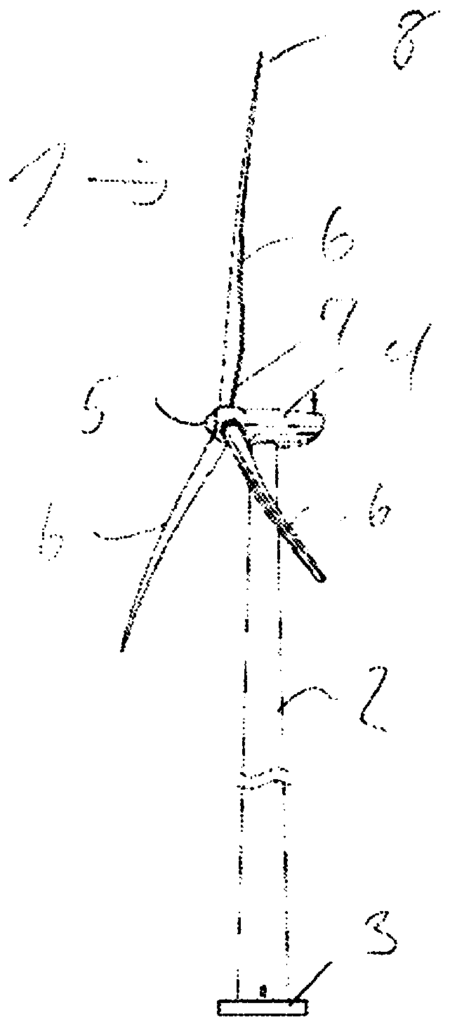
[0118] figure 1Visible in a is a typical wind turbine 1 comprising a tower 2 mounted at a foundation 3 . At the top of the tower 2 is visible a nacelle 4 comprising eg a gearbox, a generator and other components. Also installed at the nacelle 4 is a shaft for carrying the rotor, including a hub 5 and three wind generator rotor blades 6 . The rotor blade 6 is arranged at the hub 5 at a first end 7 , referred to as the root end of the rotor blade 6 . The second end 8 of the rotor blade 6 forms the blade tip.

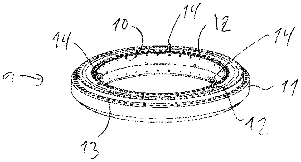
[0119] figure 2 A torque bearing 9 is shown comprising an inner ring 10 and an outer ring 11 . The inner ring is equipped with holes 12 arranged along a circle (see Figure 4 ). The outer ring also includes a plurality of holes 13 .

[0120] The holes 13 in the outer ring 11 are used to attach the torque bearing to a counterpart part on the main structure of the nacelle 4 of the wind generator. The holes 12 in the inner ring are arranged along a circle 19 (see F...


PUM


Abstract

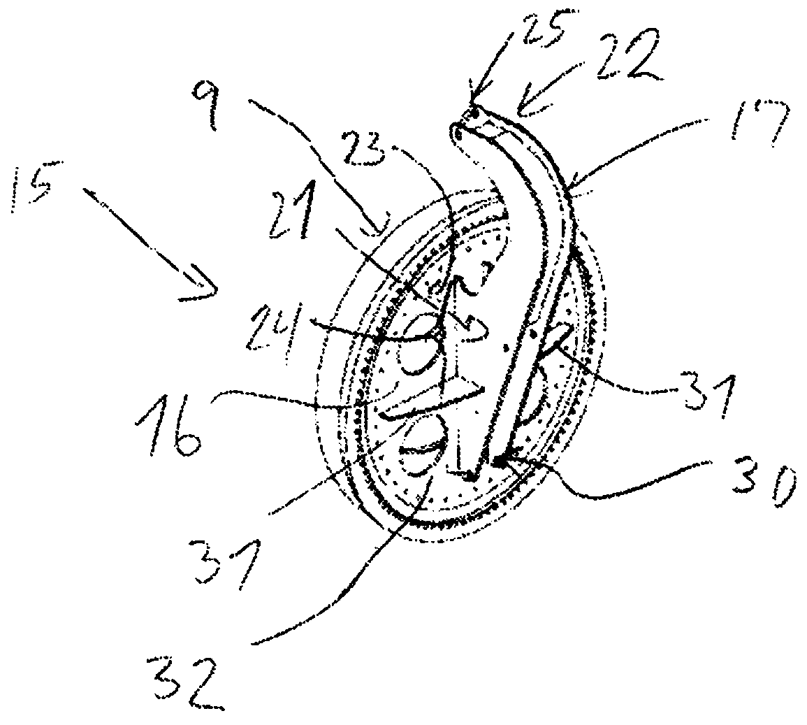
A Lifting system for moment bearing (9) of a wind turbine (1) is described, which system comprises a bearing lifting tool (15). The bearing lifting tool (15) comprises a flange (16) having a main body(32) which has a first plane Surface (18) provided with holes (20) arranged along a circle (19) and a lifting bracket (17) which has a first end (21) via an attachment area (24) being attached to a second surface (23) of the main body (32) of the flange (16) and a second end (22) extending to a position outside said circle (19) along which the holes (20) are arranged. The second end (22) of the lifting bracket (17) is provided with at least one main lifting eye (25) intended to be hooked to a crane. The main lifting eye (25) is arranged outside a gravitational plane (26) containing said firstplane surface (18) and which gravitational plane (26), in use, will be the plane in which the lifting bracket (17) is in contact with the bearing (9), preferably an inner ring (10) of the bearing (9). This system makes it possible, in an easy and secure way, to mount and dismount a moment bearing (9) of a wind turbine (1) with a rotor shaft having a tilt angle (33) different from 0 degree.

Description

technical field [0001] The present invention relates generally to the field of wind power generators, and more particularly to a torque bearing hoisting system for a wind power generator comprising a nacelle having a primary structure, a rotor, The rotor includes at least two rotor blades, each rotor blade is mounted by a root end of the rotor blade to a rotor hub, the rotor hub is connected to a torque bearing, the system includes a bearing lifting tool. [0002] Furthermore, the invention relates to a method for mounting and dismounting a torque bearing of a wind turbine bearing comprising a nacelle having a main structure, a rotor comprising at least two rotors blades, each rotor blade is mounted by the root end of the rotor blade to a rotor hub, the rotor hub is connected to the main shaft by a torque bearing, and the wind turbine has a rotor shaft, which preferably has a different at an inclination angle of 0°. [0003] Among other things, the invention relates to an ap...

Claims


Application Information

Patent Timeline
IPC IPC(8): F03D13/00F03D80/50F03D80/80
CPCF03D13/10F05B2230/61F05B2230/70F05B2240/50F03D80/50F03D80/70Y02E10/72Y02P70/50
Inventor 托马斯·克拉格·尼尔森
Owner ENVISION ENERGY DENMARK
Learn More