
Axial ball joint

A ball hinge, axial technology, applied in the direction of pivot, pivot connection, steering pull rod, etc., can solve problems such as steering impact

Inactive Publication Date: 2018-05-04
ZF FRIEDRICHSHAFEN AG
View PDF6 Cites 0 Cited by
  • Summary
  • Abstract
  • Description
  • Claims
  • Application Information

AI Technical Summary

Problems solved by technology

If the steering mechanism is introduced into the region of the end limit, the mechanical limitation of the steering amplitude leads to hard steering jerks in the region of the end

Method used


Image

  • Axial ball joint
  • Axial ball joint
  • Axial ball joint

Examples


Embodiment Construction

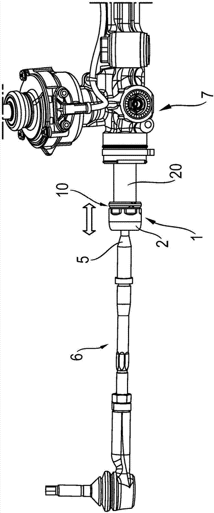
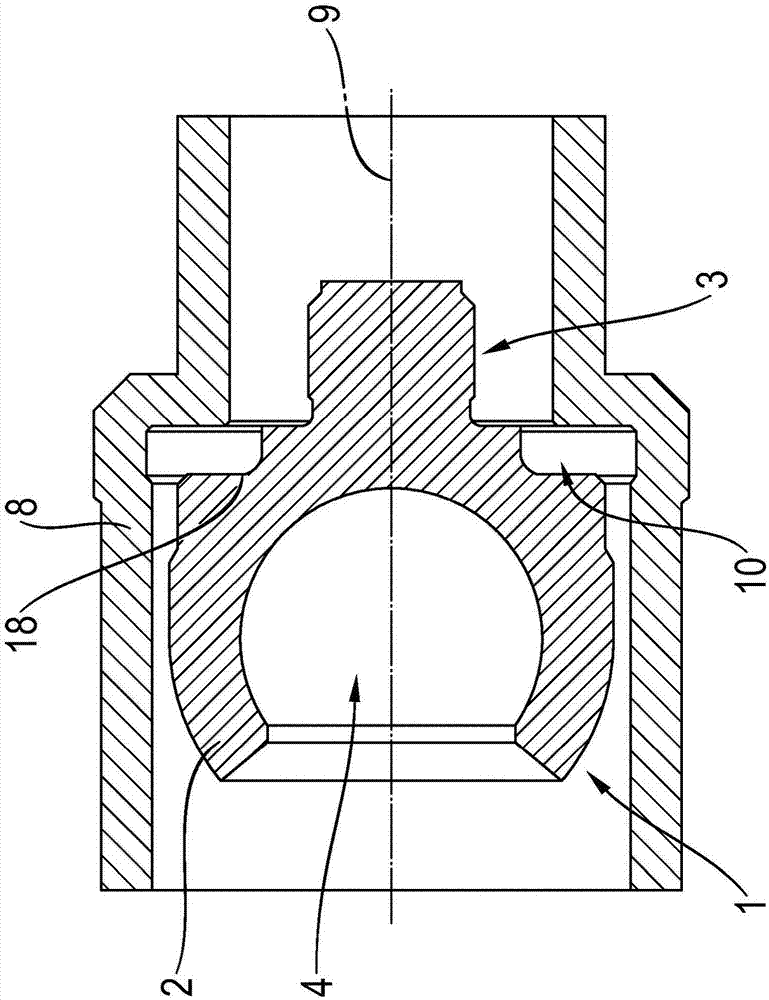
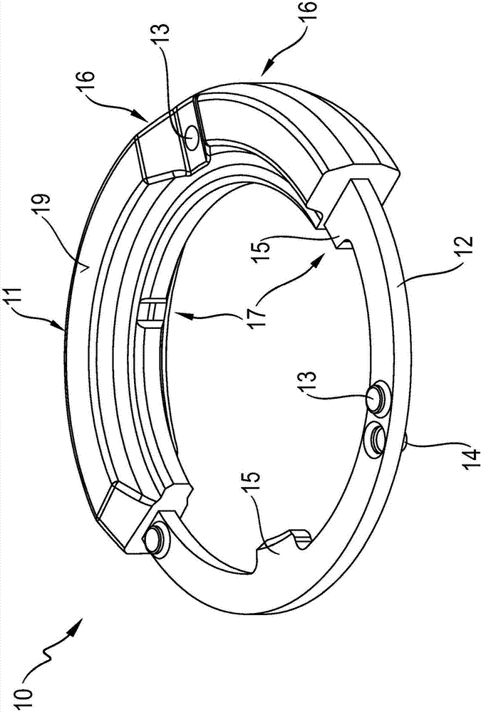
[0026] figure 1 A tie rod 6 is shown in side view, which has an axial ball joint 1 and is mechanically connected via the axial ball joint 1 to a steering gear 7 . The adjustment movement caused by the steering gear 7 brings about a displacement of the axial ball joint 1 in the direction indicated by the double arrow. The axial ball joint 1 comprises a joint housing 2 which is open on one side and which accommodates a (not shown) joint ball. The hinge ball is fastened on the hinge pin 5 , which is thus supported in a pivotable ball relative to the hinge housing 2 . A damping device 10 is arranged on the side of the hinge housing 2 facing the steering gear 7 . A damping device 10 , also called a stop damper, is mounted on the axial cup of the axial ball joint 1 . In the assembled state shown, the damper device 10 is located between the hinge housing 2 and the toothed rack 20 at the interface with the steering gear 7 .

[0027] According to the corresponding turning curve (t...


PUM


Abstract

The invention relates to an axial ball joint (1), in particular for use on a steering gear (7), comprising a joint housing (2) open on one side for receiving a joint ball (4) associated to a joint stud (5), wherein a housing stud (3) is arranged on the joint housing (2) and wherein a damping device (10) is provided on the side of the joint housing (2) provided with the housing stud (3), wherein the damping device (10) has an elastic damping element of plastic having a metal insert, wherein the metal insert is overmolded with the material of the elastic damping element.

Description

technical field [0001] The invention relates to an axial ball joint according to the preamble of claim 1 , in particular for use in a steering gear. Background technique [0002] Axial ball joints of this type are generally known from the prior art and are used in particular in vehicle steering systems. Expediently, the steering structure of the vehicle has an end limit to determine its maximum deflection. If the steering mechanism is introduced into the region of the end restriction, the mechanical limitation of the steering amplitude leads to hard steering jerks in the region of the end. In order to protect the steering gear against mechanical damage, it is known from the prior art to provide the axial ball joint associated with the tie rod with a stop damper. [0003] In this regard, reference should be made to DE 10 2008 007 107 A1, which discloses an axial ball joint for a steering gear comprising a single-sided opening for receiving a joint ball associated with a joi...

Claims


Application Information

Patent Timeline
Patent Type & Authority Applications(China)
IPC IPC(8): B62D7/16B62D7/12F16C11/06
CPCB62D7/12B62D7/163F16C11/0642F16C11/0652F16C2326/24Y10T403/32737Y10T403/32762
Inventor T·拉尔曼A·布兰克T·赫尔曼M·罗素尔
Owner ZF FRIEDRICHSHAFEN AG
Learn More