Infusion drip chamber device with replaceable dimensions

A specification and size technology, applied in the field of infusion dripping device, can solve problems such as slipping out and inapplicability of infusion dripping device

Pending Publication Date: 2020-03-27
YANCHENG JINWO MEDICAL TECH
View PDF1 Cites 2 Cited by
  • Summary
  • Abstract
  • Description
  • Claims
  • Application Information

AI Technical Summary

Problems solved by technology

[0005] The technical problem to be solved by the present invention is to provide an infusion dripping device with replaceable specifications, so as to solve the problem that in the prior art, it cannot be applied to infusion dripping devices of different sizes and slips out of smaller size infusion dripping devices. technical problem

Method used


Image

  • Infusion drip chamber device with replaceable dimensions
  • Infusion drip chamber device with replaceable dimensions
  • Infusion drip chamber device with replaceable dimensions

Examples


Embodiment 1

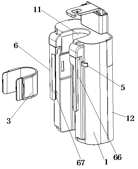
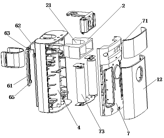
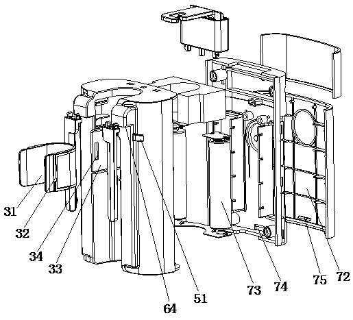
[0033] Embodiment one, with reference to Figure 1 to Figure 3It can be seen that it includes a plastic shell 1, a sensor component 2, a dropper specification and size adapting component 3, a control board, an anti-slip component 5 and a pocket clamping component 6, and one side of the plastic shell 1 is provided with a cover snap-fitted with it Plate 12, the other side of the plastic shell 1 is provided with a mounting groove 11, the mounting groove 11 in this embodiment can be a U-shaped mounting groove, the anti-slip component 5, the sensor component 2 and the pocket clamping component 6 are all arranged in the The side of the plastic housing 1 close to the installation groove 11, the installation cavity 4 is formed between the cover plate 12 and the plastic housing 1, the control main board is arranged in the installation cavity 4, and the control main board is electrically connected with the sensor component 2, and the specification of the dropping funnel The size adaptat...

Embodiment 2

[0035] Embodiment two, refer to Figure 4 As a further improvement of Embodiment 1, inflatable airbags 35 are fixedly installed on both sides of the inner surface of the shrapnel 31, and the two inflatable airbags 35 are connected through the air bag 36. An air pump 37 is arranged under the shrapnel 31, and the air pump 37 is fixed. Connect one end of the inflatable tube 38, the other end of the inflatable tube 38 passes through the shrapnel 31 and communicates with the inflatable end of one of the inflatable airbags 35, the inflatable end of the inflatable airbag 35 is provided with a one-way valve; the side wall of the installation groove 11 is provided with an inflatable In the pump placement groove 9 , after inserting the shrapnel 31 into the installation slot 33 , the air pump 37 can be placed in the air pump placement groove 9 . When monitoring the infusion dripping funnel of smaller specifications, after the medical personnel place the infusion dripping funnel in the sh...

Embodiment 3

[0036] Embodiment three, refer to Figure 5-7 , as a further improvement of the first embodiment, the present application also includes a guide clamping device 8, which is fixedly installed under the plastic housing 1, and a positioning groove 81 is opened on the guide clamping device 8. Both sides of the positioning groove 81 are provided with through holes, and both sides of the positioning groove 81 are provided with chute 82. In the chute 82, a partition block 83 is slidingly connected, and one side of the partition block 83 moves in the positioning groove 81 through the through hole. Inside, the other side of the partition block 83 is fixedly equipped with an inclined block 84, and the side of the chute 82 is fixedly equipped with a telescopic motor 85, and the driving end of the telescopic motor 85 is movably connected to one end of the telescopic rod 86, and the other end of the telescopic rod 86 is provided with The inclined surface matched by the inclined block 84; th...


PUM


Abstract

The invention discloses an infusion drip chamber device with replaceable dimensions, which belongs to the technical field of medical instruments and comprises a plastic shell, a sensor component, a drip chamber specification and dimension adapting component, a control mainboard, an anti-slip component and a pocket clamping component, and a cover plate matched with the plastic shell in a clamped manner is arranged on one side of the plastic shell. An installation groove is formed in the other side of the plastic shell, an installation cavity is formed between the cover plate and the plastic shell, a detection groove is formed in the sensor assembly, and at least one set of dripping speed sensor is installed on each of the two sides of the detection groove. The device has the advantages thatthe device can adapt to infusion drip chambers of different sizes through the drip chamber specification and size adapting assembly, medical staff can manually connect an elastic body in the prior art between two elastic body buckles to enable the elastic body to limit the infusion drip chamber in the mounting groove, the clamping hasp can clamp the edge of a pocket, therefore, the device can bestored in a pocket of a medical worker.

Description

technical field [0001] The invention relates to the technical field of medical devices, in particular to an infusion drip funnel device with replaceable sizes and specifications. Background technique [0002] Infusion is commonly known as intravenous drip, which directly injects the medicinal liquid into the vein through the infusion set, so as to obtain better and faster curative effect. At present, infusion is a very common treatment method, and in the infusion, the flow rate needs to be strictly controlled. If the infusion is too fast, it will cause an instant increase in physical burden, which is likely to cause harm to the patient's body, and even life-threatening. The infusion speed is too slow and wastes the patient's time, and some drugs have strict flow restrictions, so that a better therapeutic effect can be achieved. [0003] The invention with the publication number CN110354336A discloses an infusion flow monitoring device, which can detect the infusion flow, th...

Claims


Application Information

Patent Timeline
Patent Type & Authority Applications(China)
IPC IPC(8): A61M5/14A61M5/168
CPCA61M5/1411A61M5/16831A61M5/1689A61M2205/18A61M2205/3334
Inventor 许敬华王峻李啸扬方琼景峰
Owner YANCHENG JINWO MEDICAL TECH
Why Eureka
Try Eureka