Medical orthodontic training device

A training device and dental technology, applied in the field of training, can solve problems such as laborious use

Inactive Publication Date: 2020-03-27
BINZHOU MEDICAL COLLEGE
View PDF5 Cites 1 Cited by
  • Summary
  • Abstract
  • Description
  • Claims
  • Application Information

AI Technical Summary

Problems solved by technology

[0003] The purpose of the present invention is to solve the disadvantages of laborious use in the prior art, and propose a medical orthodontic training device

Method used


Image

  • Medical orthodontic training device
  • Medical orthodontic training device
  • Medical orthodontic training device

Examples


Embodiment 1

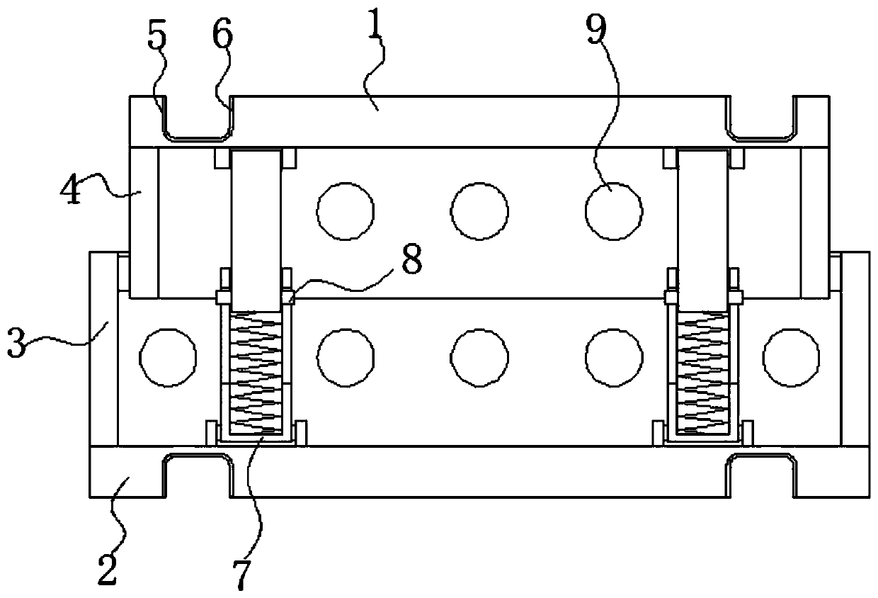
[0017] refer to Figure 1-3 , a medical orthodontic training device, comprising an upper plate 1 and a lower plate 2, the upper plate 1 and the lower plate 2 are arranged in parallel up and down, the lower connecting plate 3 is fixed on the upper side of the lower plate 2, and the lower connecting plate 3 is fixed on the bottom side of the upper plate 1 The upper connecting plate 4 is fixed, and the upper connecting plate 4 and the lower connecting plate 3 are connected to each other in rotation. The upper connecting plate 4 and the lower connecting plate 3 are provided with a plurality of ventilation holes 9, the top of the upper plate 1 and the bottom of the lower plate 2 Both are provided with a tooth-shaped annular groove 5, and latex 6 is fixed on the inner wall of the tooth-shaped annular groove 5, and telescopic mechanisms 7 are connected on both sides between the upper plate 1 and the lower plate 2. When in use, the device is first placed in the oral cavity, and then th...

Embodiment 2

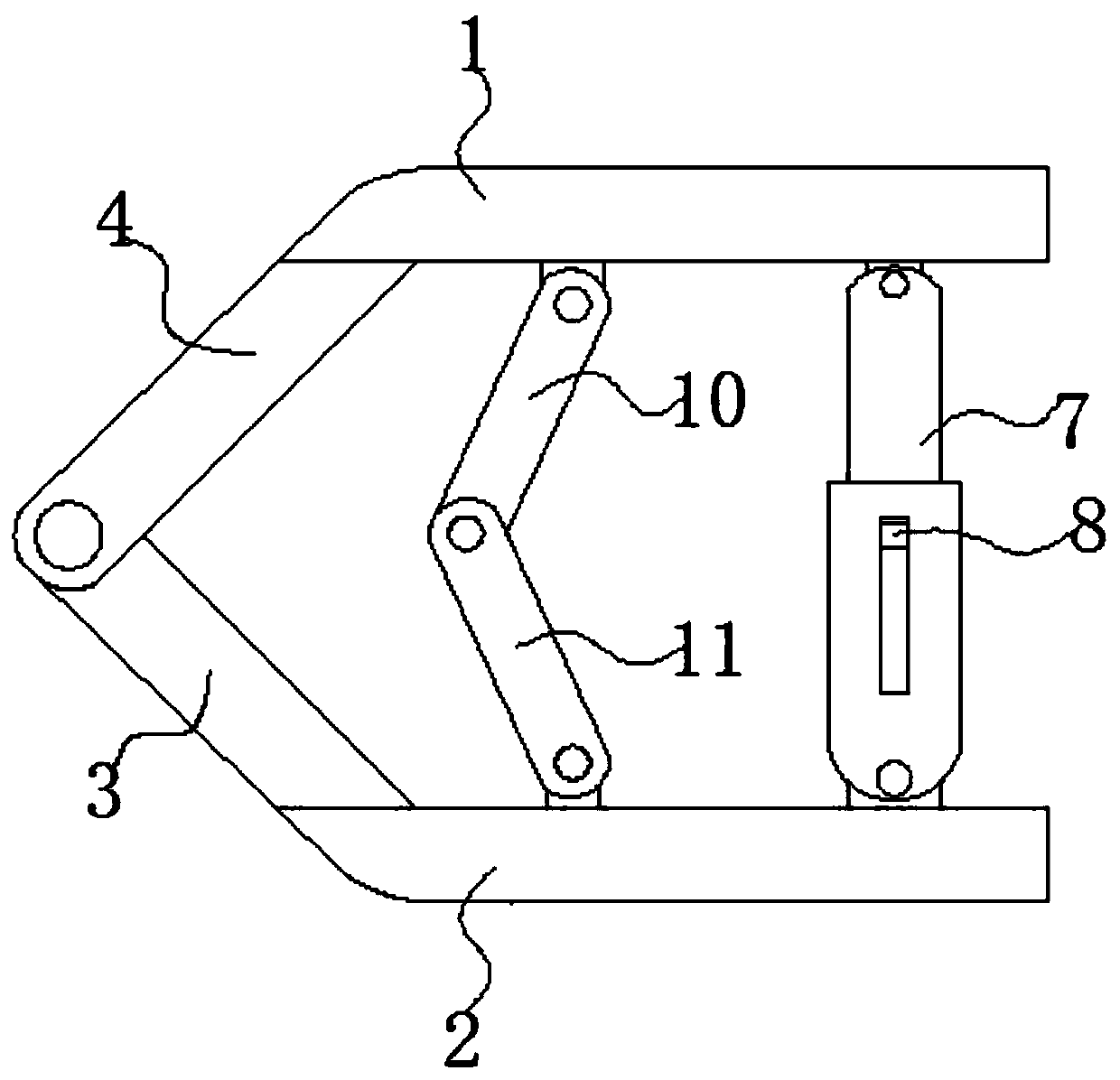
[0020] refer to figure 2 , as another preferred embodiment of the present invention, the difference from Embodiment 1 is that both sides below the upper plate 1 are rotatably connected with upper rods 10, both sides above the lower plate 2 are rotatably connected with lower rods 11, and the lower rods 11 and the upper rod 10 are rotatably connected to each other, and the connection between the lower rod 11 and the upper rod 10 can support between the upper plate 1 and the lower plate 2 .

Embodiment 3

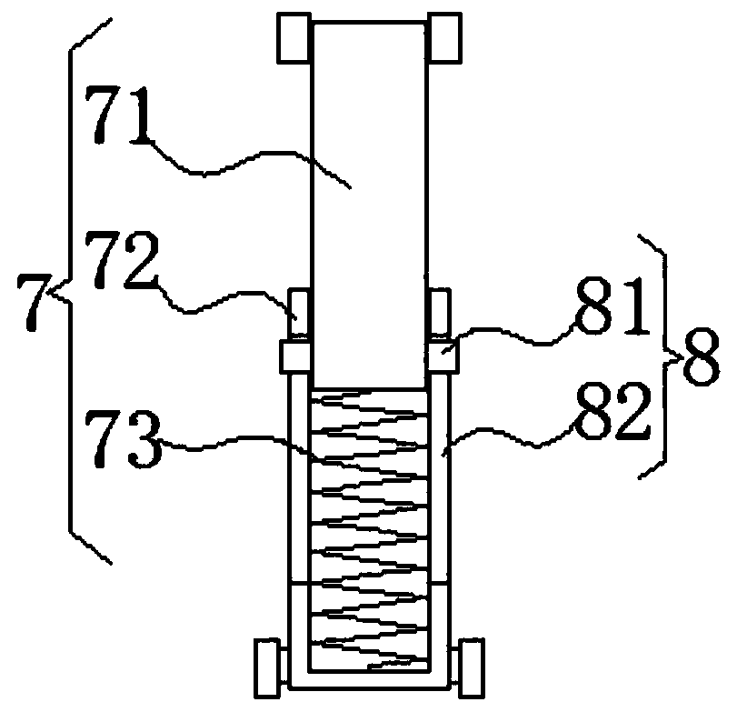
[0022] refer to Figure 2-3 , as another preferred embodiment of the present invention, the difference from Embodiment 1 is that the sliding limit mechanism 8 includes a sliding plate 81 and a sliding hole 82, the sliding holes 82 are opened on both sides of the sleeve 72, and the sliding plate 81 is fixed on the insertion rod 71 On both sides, and one end of the sliding plate 81 passes through the sliding hole 82 and extends outward, and the sliding of the sliding plate 81 in the sliding hole 82 can limit the insertion rod 71 .


PUM


Abstract

The invention relates to the technical field of training, in particular to a medical orthodontic training device. The medical orthodontic training device comprises an upper plate and a lower plate, wherein the upper plate and the lower plate are arranged in parallel up and down; a lower connecting plate is fixed to one side of the upper portion of the lower plate. An upper connecting plate is fixed on one side of the bottom of the upper plate; the upper connecting plate and the lower connecting plate are rotationally connected with each other; tooth-shaped annular grooves are formed in the upper portion of the upper plate and the lower portion of the lower plate. Telescopic mechanisms are connected to the two sides between the upper plate and the lower plate; the telescopic mechanisms comprise inserting rods and sleeves, the bottoms of the sleeves are rotationally connected to the two sides of the upper portion of the lower plate, the upper portions of the inserting rods are rotationally connected to the two sides of the lower portion of the upper plate, one ends of the inserting rods are inserted into the sleeves, and sliding limiting mechanisms are connected to the two sides between the inserting rods and the sleeves. According to the orthodontic training device, the device is placed in the oral cavity, and then teeth are placed in the tooth-shaped annular grooves in the upper plate and the lower plate.

Description

technical field [0001] The invention relates to the technical field of training, in particular to a medical orthodontic training device. Background technique [0002] The mouth is the beginning of the digestive tract. The front fissure communicates with the outside world, and the back passes through the pharynx to continue with the pharynx. There are teeth, tongue and other organs in the oral cavity. The front wall of the oral cavity is the lips, the side wall is the cheeks, the roof is the palate, and the floor of the mouth is the mucosa and muscles. The oral cavity in the hospital may be deformed due to some reasons in the closure of the oral cavity. In order to train it, we have proposed an orthodontic training device, but the existing training device is relatively laborious to use. Contents of the invention [0003] The object of the present invention is to solve the shortcoming of laborious use in the prior art, and propose a medical orthodontic training device. ...

Claims


Application Information

Patent Timeline
Patent Type & Authority Applications(China)
IPC IPC(8): A63B23/025A63B21/05
CPCA63B21/05A63B23/025
Inventor 高晓丽
Owner BINZHOU MEDICAL COLLEGE
Why Eureka
Try Eureka