[0028] The following will clearly and completely describe the technical solutions in the embodiments of the present invention with reference to the accompanying drawings in the embodiments of the present invention. Obviously, the described embodiments are only some, not all, embodiments of the present invention. Based on the embodiments of the present invention, all other embodiments obtained by persons of ordinary skill in the art without making creative efforts belong to the protection scope of the present invention.
[0029] In this application, the term "comprises", "comprises" or any other variation thereof is intended to cover a non-exclusive inclusion such that a process, method, article, or apparatus comprising a set of elements includes not only those elements, but also includes none. other elements specifically listed, or also include elements inherent in such a process, method, article, or apparatus. Without further limitations, an element defined by the phrase "comprising a ..." does not exclude the presence of additional identical elements in the process, method, article or apparatus comprising said element.
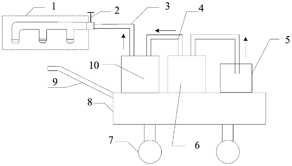
[0030] The embodiment of the present invention provides a fireproof paint spraying device for cables, see figure 1 and figure 2 , is a structural schematic diagram of a fireproof paint spraying device for cables according to an embodiment of the present application, including: a special atomizing nozzle 1, a connecting pipe 3, a paint container 5, a high-pressure pump 6 and a pressure accumulation filter 10;
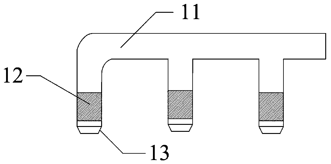
[0031] The special atomizing nozzle 1 includes: an interface 12, a paint pipeline 11 and several paint nozzles 13;
[0032] The paint nozzle 13 is detachably connected to the paint pipeline 11 through the interface 12, so that the paint nozzle 13 can be flexibly replaced according to different usage conditions and application scenarios;
[0033] It should be noted that the number of the interfaces 12 is the same as the number of the paint nozzles 13 , and each paint nozzle 13 is connected to the paint pipeline 11 through an interface 12 .
[0034] It should also be noted that the paint nozzles 13 are arranged on the paint pipeline 11 through the interface 12 at preset intervals, and the fireproof paint can be evenly sprayed on the cable through several paint nozzles 13 .
[0035] The special atomizing nozzle 1 is connected to one end of the pressure accumulation filter 10 through the connecting pipe 3;
[0036] The other end of the pressure accumulator filter 10 is connected to the paint container 5 through the high-pressure pump 6, and the high-pressure pump 6 is used to transport the paint in the paint container 5 to the paint nozzle 13 to carry out cable spraying.
[0037] It should be noted that the pressure accumulator filter 10 can play the role of filtering large particles of fireproof paint, avoid blocking the atomizing nozzle 1, and can increase the pressure of the atomizing nozzle 1 at the same time, thereby improving the effect of the atomizing nozzle 1 on the fireproof coating. Atomization effect.
[0038] The high-pressure pump 6 is connected to the paint container 5, and can transport the fireproof paint in the paint container 5 to the pressure accumulation filter 10 for filtering and accumulating pressure, and the filtered fireproof paint enters under the pressure provided by the high-pressure pump 6. The coating nozzle 13 of the special spray head 1 is atomized, and the atomized fireproof coating is sprayed on multiple cables through several coating nozzles.
[0039] In order to facilitate understanding of the above solution, an example is used below for illustration.
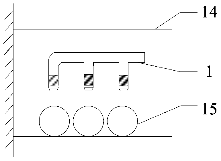
[0040] like image 3 As shown, the special atomizing nozzle 1 adopts 3 paint nozzles 13, and the 3 paint nozzles are connected with the paint pipeline 11 through the interface 12, and the special nozzle sprays the fireproof paint on the 3 cables 15.
[0041] It should be noted that three cables 15 are sprayed by using the cable fireproof paint spraying device disclosed in the present invention. During the spraying process, the staff only needs to follow the direction of the cables 15, and each paint nozzle 13 is aimed at one cable 15 spraying, only 3 cables 15 need to be sprayed once, and there is no need for staff to spray the cables 15 back and forth. Therefore, the spraying efficiency of the cables can be effectively improved through the electric current fireproof paint spraying device disclosed in this application.
[0042] The special atomizing nozzle of the embodiment of the present application is composed of an interface, a paint pipeline and several paint nozzles; the paint nozzle is connected to the paint pipeline through the interface; the special atomizing nozzle is connected to the One end of the pressure accumulation filter is connected; the other end of the pressure accumulation filter is connected with the paint container through the high pressure pump, and the high pressure pump is used to transport the paint in the paint container to the paint nozzle pair Cables are sprayed. Through the fireproof paint spraying device for cables disclosed above, multiple paint nozzles in the special atomizing spray head are set, and fireproof paint is sprayed on multiple cables along the direction of the cables, effectively improving the spraying efficiency of the cables .
[0043] The paint pipeline 11 is made of aluminum alloy.
[0044] It should be noted that, in this application, the material of the paint pipe 11 may be aluminum alloy or other materials, but the material of the paint pipe 11 is not limited to aluminum alloy.
[0045] Further, the interface 12 is a telescopic interface.
[0046] It should be noted that when multiple cables are combined together, they are not arranged in a straight line, and several paint nozzles 13 need multiple cables to spray at one time, and the distance between the paint nozzle 13 and the cables needs to be controlled within a certain range Therefore, it is necessary to adjust the distance of each paint nozzle 13 corresponding to multiple cables in several paint nozzles 13, so that the corresponding distance of each group should be kept within a certain range, so that the paint nozzle 13 can achieve the best coating effect on the cables. .
[0047] Further, the interface 12 is a telescopic adjustable threaded pipe.
[0048] It should be noted that the telescopic adjustable interface can adjust the orientation of the paint nozzle 13 and the distance from the cable, so that the paint nozzle 13 can better spray fireproof paint on multiple cables at one time. The materials are realized and will not be repeated here.
[0049] For ease of understanding, such as Figure 4 As shown, the fireproof coating is sprayed when 3 cables are overlapped.
[0050] When the three cables 15 are overlapped and combined, and the special atomizing nozzle 1 using three paint nozzles 13 needs to spray the three cables 15 once, the paint nozzles 13 on both sides of the three paint nozzles 13 need to be stretched, And adjust the orientation of the paint nozzle 13 so that its special atomizing spray head 1 can spray three cables at one time along the direction of the cables 15 .
[0051] Further, the number of the interfaces 12 and the paint nozzles 13 is multiple in one-to-one correspondence, and the multiple interfaces 12 are arranged equidistantly in the paint pipeline 11 along a straight line.
[0052] It should be noted that, since multiple cables need to be sprayed, and multiple cables are arranged and combined together, in the case of the same diameter of each cable, each paint nozzle 13 is aimed at one cable for spraying, so it is necessary to spray The plurality of interfaces 12 are arranged equidistantly in the paint pipeline 11 along a straight line, so that the paint nozzles connected to the interfaces can spray the corresponding cables, thereby improving the spraying efficiency and effect of multiple cables.
[0053] Further, the connecting pipe 3 is a hose.
[0054] It should be noted that since the special atomizing nozzle 1 needs to spray fireproof coatings on the cables in different height scenes, and some cables are set at very high places, the special atomizing nozzle 1 is required to be able to move easily, that is, the connecting pipe 3 is set as a hose, so as to meet the use requirements of the special atomizing nozzle 1.
[0055] Further, the fireproof paint spraying device for cables also includes: a flow regulating valve 2 arranged on the special atomizing nozzle 1 .
[0056] It should be noted that the atomization effect of the fireproof coating and the amount of the fireproof coating during atomization can be controlled by adjusting the flow regulating valve 2 .
[0057] Further, the fireproof paint spraying device for cables also includes: a movable workbench;
[0058] The paint container 5, the high-pressure pump 6 and the pressure accumulation filter 10 are arranged on the movable workbench.
[0059] It should be noted that by arranging a movable workbench, and setting the high-pressure pump 6 and the pressure accumulator filter 10 on the movable workbench, the spraying device disclosed in the present application can be moved conveniently, reducing the staff's concern for the spraying process. The difficulty of moving the device can effectively improve the spraying efficiency of the staff.
[0060] Further, the movable workbench includes: a workbench 8, handrails 9 and rollers 7;
[0061] The rollers 7 are arranged at the bottom of the workbench 8 , and the handrails 9 are arranged at one side of the workbench 8 .
[0062] It should be noted that the push armrest 9 provides a focus point for the staff to move the workbench 8. By setting the rollers 7 under the workbench 8, the staff pushes and pulls the workbench through the handrail 9, Under the rotation of the roller 7, the staff can move the workbench 8 more conveniently, reduce the difficulty of the staff to move the workbench, reduce the time for the staff to move the workbench, thereby effectively improving the spraying efficiency of the staff.
[0063] Further, the roller 7 is a universal wheel.
[0064] It should be noted that setting the roller 7 as a universal wheel can make the workbench 8 move in any direction under the push and pull of the staff, so that the staff can reduce the difficulty and time of moving the workbench, thereby effectively improving the work efficiency. Efficiency of personnel moving workstations.
[0065] In order to facilitate the understanding of the above scheme, combined with Figure 1 to Figure 4 , below in conjunction with specific embodiment this scheme is further introduced:
[0066] A fireproof paint spraying device for cables, comprising: a special atomizing nozzle, a flow regulating valve, a hose connecting the nozzle, a high-pressure pump and the like.
[0067] 1 means a special atomizing nozzle. According to different application scenarios, it is designed as 3 paint nozzles. The paint nozzles are arranged at equal intervals, and the nozzles and the nozzle body are connected by telescopic adjustable threaded pipes.
[0068] 2 represents the flow regulating valve, which can control the atomization effect of the fireproof coating by adjusting the opening of the flow valve.
[0069] 3 means connecting the nozzle hose, and the length of the hose can be flexibly selected according to the actual needs of the site.
[0070] 4 represents the connecting pipe.
[0071] 5 represents a paint container.
[0072] 6 indicates that the high-pressure pump sucks out the paint in the container and delivers it to the pressure accumulation filter.
[0073] 7 represents scroll wheel.
[0074] 8 represents a workbench.
[0075] 9 represents pushing handrail.
[0076] 10 represents a pressure accumulator filter, and the pressure accumulator filter plays the role of filtering large-particle paint, avoiding clogging of the atomizing nozzle, and simultaneously increasing the pressure at the atomizing nozzle to improve the atomization effect of the paint.
[0077] 11 represents paint pipe.
[0078] 12 indicates the interface, which can be specifically a telescopic adjustable threaded pipe. For the application scene of the cable, a threaded pipe is added at the front end of the paint outlet. The threaded pipe can flexibly adjust the outlet direction and length of the paint, and is suitable for use in narrow spaces. use.
[0079] 13 represents a paint nozzle, and the hole diameter of the paint nozzle can be flexibly selected according to different usage conditions and application scenarios.
[0080] 14 represents a cable support.
[0081] 15 represents a cable.
[0082] work process:
[0083] Prepare the fireproof paint in the paint container 5 before construction, and adjust the interface 12 (telescopic adjustable threaded pipe) to an appropriate position according to the different cable laying methods (the invention provides two typical cable layout diagrams) to ensure The paint nozzle 13 is basically perpendicular to the direction of the cable, and the distances between the three nozzles and the cable are basically the same. Start the high-pressure pump 6, and the high-pressure pump 6 will suck the fireproof paint into the pressure accumulation filter 10, and after being filtered by the pressure accumulation filter 10, the fireproof paint will reach the flow regulating valve 2, and the flow rate will control the mist of the fireproof paint by adjusting the flow regulating valve 2. effect. After the fireproof paint reaches the paint nozzle 13, it is atomized under the action of high air pressure, and the paint nozzle 13 can flexibly adjust its position and direction according to different application scenarios. The path of the fire retardant coating has been marked with arrows in the figure.
[0084] Compared with the prior art, the advantages of the device and technical method include:
[0085] First, compared with manual brushing and traditional mechanical spraying, the three-nozzle structure can greatly improve the spraying efficiency of fire retardant coatings.
[0086] Second, the paint-specific nozzles can be flexibly adjusted to achieve effective spraying in narrow spaces, suitable for various application scenarios, and avoid the occurrence of missed spraying.
[0087] Each embodiment in this specification is described in a progressive manner, the same and similar parts of each embodiment can be referred to each other, and each embodiment focuses on the differences from other embodiments. In particular, for the system or the system embodiment, since it is basically similar to the method embodiment, the description is relatively simple, and for relevant parts, please refer to the part of the description of the method embodiment. The systems and system embodiments described above are only illustrative, and the units described as separate components may or may not be physically separated, and the components shown as units may or may not be physical units, that is It can be located in one place, or it can be distributed to multiple network elements. Part or all of the modules can be selected according to actual needs to achieve the purpose of the solution of this embodiment. It can be understood and implemented by those skilled in the art without creative effort.
[0088] Professionals can further realize that the units and algorithm steps of the examples described in conjunction with the embodiments disclosed herein can be implemented by electronic hardware, computer software or a combination of the two. In order to clearly illustrate the possible Interchangeability, in the above description, the components and steps of each example have been generally described according to their functions. Whether these functions are executed by hardware or software depends on the specific application and design constraints of the technical solution. Those skilled in the art may use different methods to implement the described functions for each specific application, but such implementation should not be regarded as exceeding the scope of the present invention.
[0089] The above description of the disclosed embodiments is provided to enable any person skilled in the art to make or use the invention. Various modifications to these embodiments will be readily apparent to those skilled in the art, and the general principles defined herein may be implemented in other embodiments without departing from the spirit or scope of the invention. Therefore, the present invention will not be limited to the embodiments shown herein, but is to be accorded the widest scope consistent with the principles and novel features disclosed herein.