
Creep age forming method based on mechanical loading

A creep aging forming and mechanical loading technology, applied in the field of aerospace manufacturing engineering, can solve the problems of difficult mold repair, complex structure, poor forming adaptability of multi-curvature parts, etc., so as to reduce the possibility of internal defects and reduce production costs. , Overcome the effect of local deformation

Active Publication Date: 2020-03-27
CENT SOUTH UNIV
View PDF12 Cites 11 Cited by
  • Summary
  • Abstract
  • Description
  • Claims
  • Application Information

AI Technical Summary

Problems solved by technology

Chinese invention patent CN102266887B discloses a mold-shaped plate-type mechanically loaded creep aging forming device. The upper mold adopts a dot-matrix loading method to rise and fall, the structure is complicated, and it is inconvenient for automatic control, and the pillar and the workpiece are in point contact. Formed parts are prone to internal damage; the lower die adopts a mold-shaped plate type, which is not easy to repair and has poor adaptability to the forming of multi-curvature parts
[0004] Chinese invention patent application CN110052520A discloses a combined mechanically loaded creep aging forming device, in which the punch and die are hinged by a plurality of two-way die-shaped plate connection units; in the loading state, the middle part of the punch and die is combined The shape of the curved surface of the mold plate is not easy to control, and it is difficult to ensure that the shape of the die is the target surface

Method used


Image

  • Creep age forming method based on mechanical loading
  • Creep age forming method based on mechanical loading
  • Creep age forming method based on mechanical loading

Examples


Embodiment Construction

[0036] The embodiments of the present invention will be described in detail below with reference to the accompanying drawings, but the present invention can be implemented in various ways defined and covered by the claims.

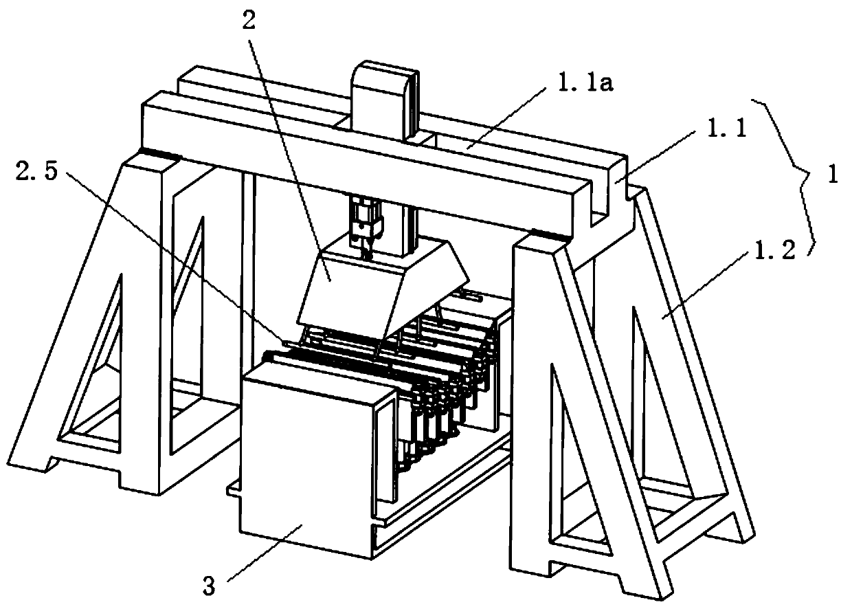
[0037] A creep age forming method based on mechanical loading, using such as figure 1The shown mechanically loaded creep aging forming device mechanically loads the aluminum alloy sheet, and the forming device includes a frame 1, a loading device 2 arranged on the frame, and a mold 3 arranged under the loading device; the frame includes a beam 1.1 And the legs 1.2 arranged at the bottom of both ends of the beam, the beam is provided with a through hole along the vertical direction, and the top of the beam is provided with a groove 1.1a along its length direction.

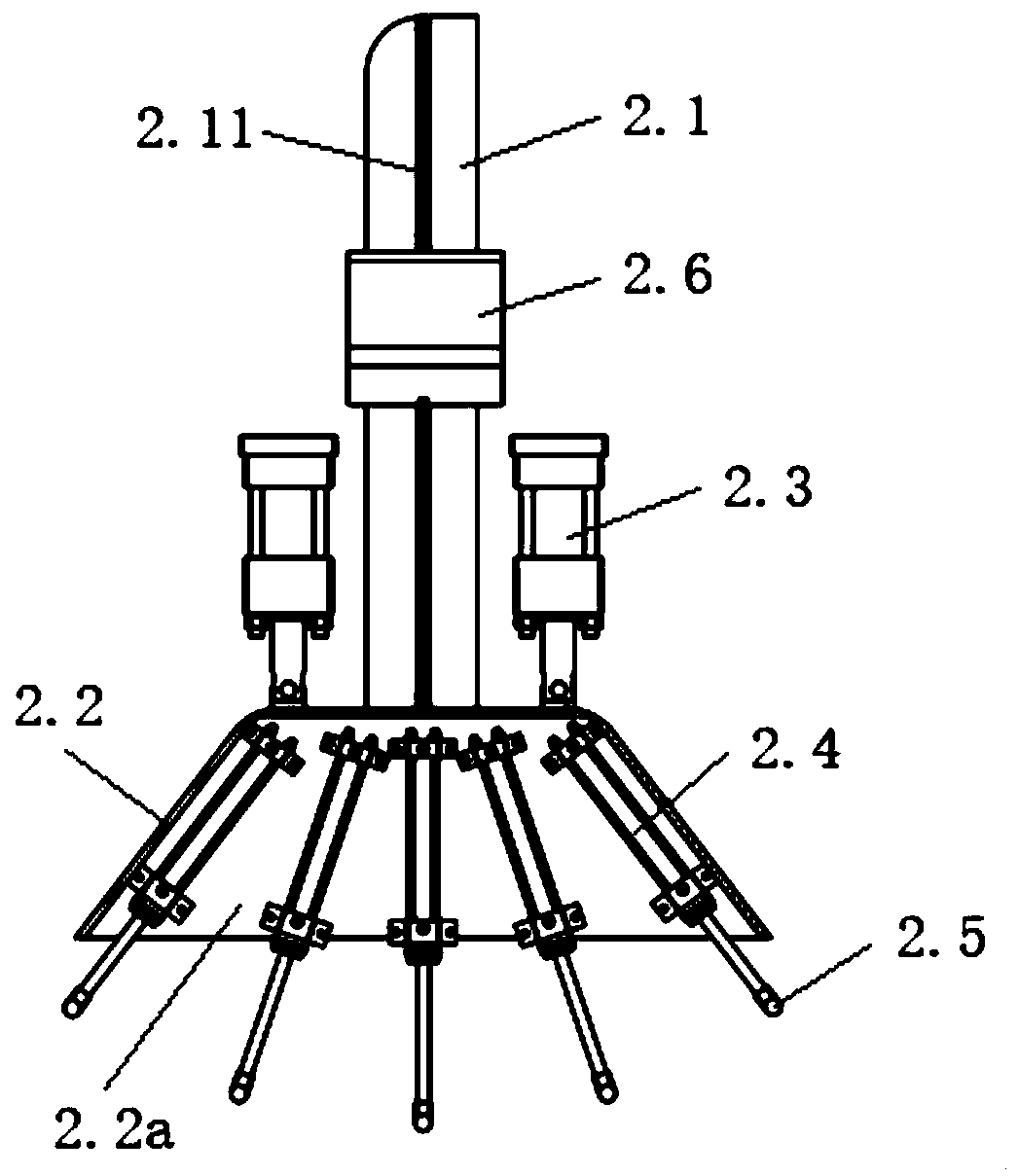
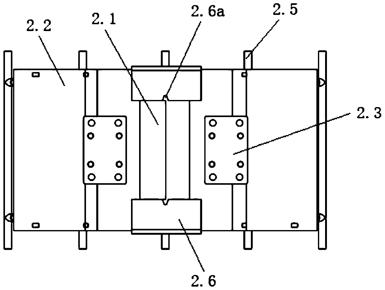
[0038] to combine Figure 2 to Figure 4 As shown, the loading device 2 includes a guide rod 2.1, a skirt bracket 2.2, a main hydraulic cylinder 2.3 and multiple sets of loading hydraulic cylind...


PUM


Abstract

The invention discloses a creep age forming method based on mechanical loading. A mechanical-loading creep age forming device is used for carrying out mechanical loading on an aluminum alloy plate, and the forming method comprises the following steps that 1, a to-be-formed plate is placed on a die; 2, firstly, loads are applied to the upper surface of the to-be-formed plate through a main hydraulic cylinder and a loading hydraulic cylinder, so that the to-be-formed plate is deformed until the lower surface of the to-be-formed plate is tightly attached to the upper surface of a die shape plate,and then the to-be-formed workpiece is fixed to a die profile through a cover plate; 3, the to-be-formed workpiece and the die are placed in a hot-press pot, and the temperature is increased to an aging temperature and is kept; and 4, after cooling to room temperature, the workpiece after creep aging forming is unloaded and obtained. According to the forming method, the aluminum alloy plate is pressurized in a mechanical loading mode, so that a plurality of workpieces with different curvatures can be formed, and compared with vacuum film pasting in the prior art, the pre-preparation time canbe reduced by about 30%.

Description

technical field [0001] The invention relates to the technical field of aerospace manufacturing engineering, in particular to a creep aging forming method based on mechanical loading. Background technique [0002] With the development of aluminum alloy integral wall panels in the direction of large curvature, high-strength thin skin, traditional room temperature forming methods such as gate pressing, rolling bending, stretching, and shot blasting can no longer meet the precise shape manufacturing requirements of integral wall panels. As a processing method suitable for the forming of aluminum alloy integral panels, creep aging forming is based on the characteristics of material creep and aging, and combines aging heat treatment and forming process to simultaneously realize the forming of the shape and performance requirements of the part. craft. First of all, the workpiece is elastically deformed by a certain loading method at room temperature, and this deformation is mainta...

Claims


Application Information

Patent Timeline
IPC IPC(8): B21D31/00C22F1/04C21D8/00
CPCB21D31/00C21D8/00C22F1/04
Inventor 湛利华彭南辉徐永谦杨有良
Owner CENT SOUTH UNIV
Learn More