

Novel ball pair mechanism and multi-degree-of-freedom composite ball pair joint hinge
A ball pair and hinge technology, which is applied in the field of new ball pair mechanism and multi-degree-of-freedom compound ball joint joint hinge, can solve the problems of complex ball pair structure and small range of motion, and achieve a large range of motion, improved performance, and improved motion space Effect
- Summary
- Abstract
- Description
- Claims
- Application Information
AI Technical Summary
Problems solved by technology
Method used
Image

Examples
specific Embodiment approach 1
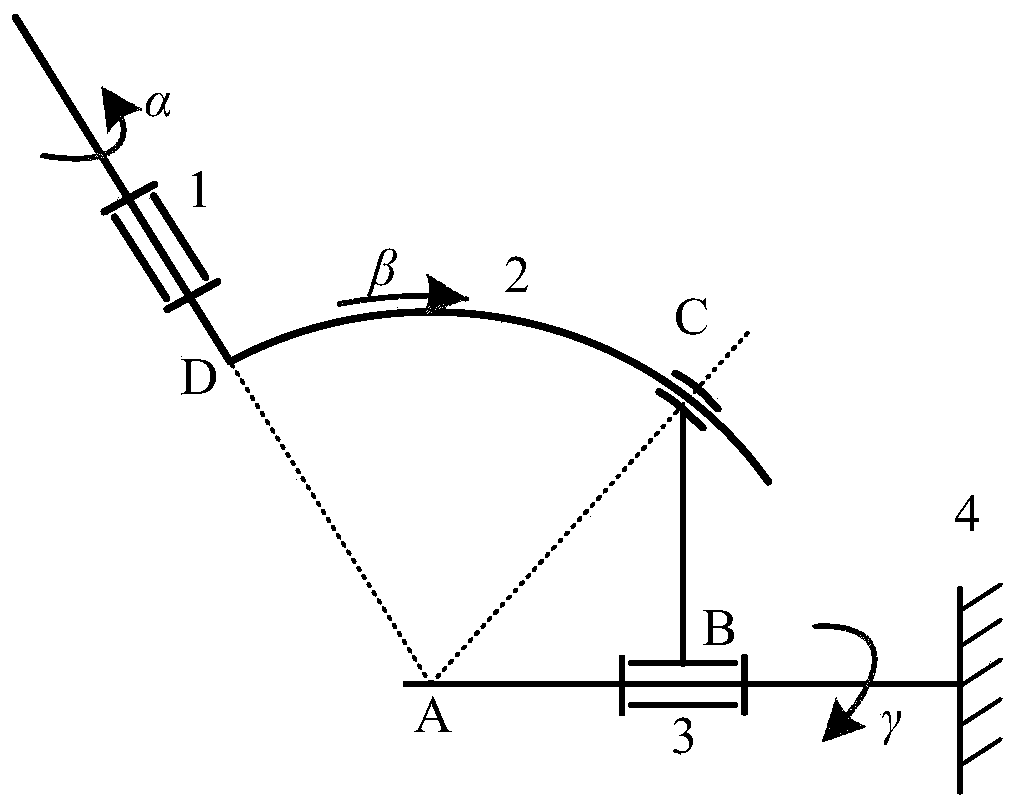
[0038] Specific implementation mode one: refer to figure 1 Describe this embodiment in detail. A ball pair mechanism described in this embodiment includes at least one rotation group, and the rotation group includes: a rod rotation connection part 1, a pitch rotation connection part 2, a roll rotation connection part 3 and Rack 4;
[0039] The rod rotation connecting part 1 and the pitching rotation connecting part 2 are connected in rotation;
[0040] The pitch rotation connection part 2 and the roll rotation connection part 3 are connected by a moving pair, and the moving pair is arc-shaped;
[0041] The roll rotation connecting part 3 is connected to the frame 4 in rotation;
[0042] The axes of the rod rotation connecting part 1 and the roll rotation connecting part 3 and the arc trajectory axis of the pitch rotation connecting part 2 intersect at one point.
specific Embodiment approach 2
[0043] Embodiment 2: This embodiment is a further description of Embodiment 1. The difference between this embodiment and Embodiment 1 is that there are multiple rotating groups, and the rotating groups are connected through a connecting mechanism.
specific Embodiment approach 3
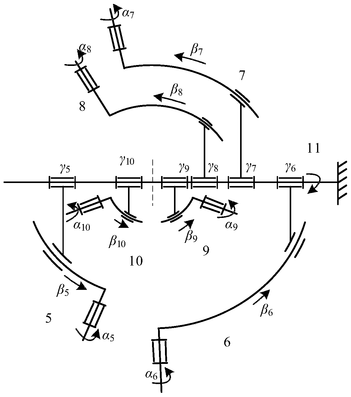
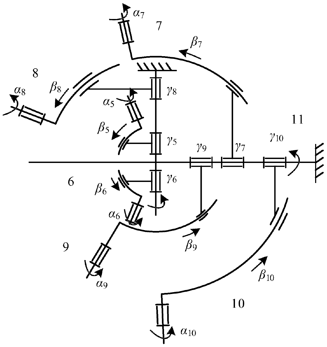
[0044] Embodiment 3: This embodiment is a further description of Embodiment 2. The difference between this embodiment and Embodiment 2 is that the connecting mechanism is a support member 11, and the mechanism is connected to on the support member 11. Such as figure 2 and image 3 shown.
[0045] Each individual new ball pair mechanism is connected to the support member 11 by rolling to form a freely rotatable connection. Similarly, according to the analysis of the above-mentioned new ball pair mechanism, the intersection points of the axes of each single new ball pair mechanism in the composite ball pair mechanism combined by the new ball pair mechanism are coincident, ensuring that the center of motion does not change.
PUM
 Abstract
Description
Claims
Application Information