Supercharge Your Innovation With Domain-Expert AI Agents!

Planetary reducer for coaxial propeller reversing helicopter

A technology of planetary reducer and helicopter, which is applied in the direction of unmanned aircraft, aircraft, rotorcraft, etc., and can solve the problem of inability to realize dual-rotor coaxial reverse rotation

Pending Publication Date: 2020-03-27
一飞(海南)科技有限公司
View PDF1 Cites 2 Cited by
  • Summary
  • Abstract
  • Description
  • Claims
  • Application Information

AI Technical Summary

Problems solved by technology

Various planetary reducers are widely used in manned helicopters, but general planetary reducers cannot realize the function of double-rotor coaxial reverse rotation

Method used


Image

  • Planetary reducer for coaxial propeller reversing helicopter
  • Planetary reducer for coaxial propeller reversing helicopter

Examples


Embodiment 1

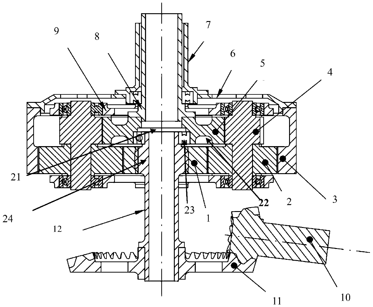
[0024] A planetary reducer for a coaxial anti-propeller helicopter of the present invention comprises an intermediate transmission shaft 12, a first-stage sun gear 1 fixed on the top of the intermediate transmission shaft, a plurality, such as three or four, and the above-mentioned The first-stage planetary gear 2 meshed with the first-stage sun gear, the first-stage ring gear 3 meshed with the first-stage planetary gear, and the connecting frame 6 that fixedly connects the first-stage inner ring gear with the outer shaft , a plurality of secondary planetary gears 4 arranged coaxially with the first-stage planetary gears, the secondary sun gears 4 coaxially arranged above the primary sun gear and meshed with the second-stage planetary gears in a relatively rotatable manner 5. The secondary sun gear is connected to the inner shaft through transmission, and the coaxial upper and lower ends of the primary planetary gear and secondary planetary gear are respectively set up and down...

Embodiment 2

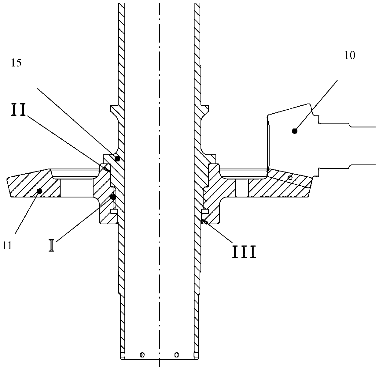
[0031] The lower end of the intermediate transmission shaft is fixedly provided with a bevel gear 11 and a bevel gear shaft 10 matched with the bevel gear, and the power end of the bevel gear shaft is fixedly connected with the engine through a coupling. The lower flange 15 of the bevel gear is arranged on the said intermediate transmission shaft, the upper part of the central hole of the said bevel gear is in interference fit with the said intermediate transmission shaft, and the middle part is in interference fit with the said intermediate transmission shaft. The shaft spline fits, and the lower part transition fits with the intermediate transmission shaft. The shaft intersection angle of the bevel gear and the bevel gear shaft is 80°-90°. That is, the shaft angle of a pair of bevel gears can be 90 degrees or not 90 degrees, so that the input shaft can be inclined in different directions to adapt to different installation positions of the engine; or the output shaft of the r...


PUM


Abstract

The invention discloses a planetary reducer for a coaxial propeller reversing helicopter. The planetary reducer comprises an intermediate transmission shaft, a primary sun gear fixed to the top of theintermediate transmission shaft, multiple primary planet gears in engaged connection with the primary sun gear, a primary inner gear ring engaged with the primary planet gears, a connecting frame forfixedly connecting the primary inner gear ring with an outer shaft, multiple secondary planet gears coaxial with the primary planet gears and a secondary sun gear which is coaxially arranged above the primary sun gear in a relatively-rotating manner and is in engaged transmission with the secondary planet gears. The secondary sun gear is in transmission connection with an inner shaft, the primaryplanet gears and the secondary planet gears are coaxially arranged in a one-to-one up-and-down correspondence manner, and the coaxial upper ends and lower ends of the primary planet gears and the secondary planet gears are rotationally connected with a fixed planet carrier. The reducer is provided with a group of primary planet gear train including one sun gear, the multiple planet gears and oneinner gear ring and a group of secondary planet gear train including one sun gear and the multiple planet gears and not including an inner gear ring. The reducer is provided with one fixed planet carrier shared by the primary planet gear train and the secondary planet gear train.

Description

technical field [0001] The invention belongs to the technical field of mechanical transmission devices, and in particular relates to a planetary reducer for a coaxial reverse propeller helicopter. Background technique [0002] The structural characteristics of the coaxial reverse dual-rotor are: two inputs + two outputs, that is, the entire transmission device has two power input shafts, which are respectively driven by two engines or electric motors, and two power output shafts output power externally. Two power input shafts drive two coaxial power output shafts through two sets of independent reduction gear mechanisms, and each power output shaft is connected to a rotor, thus forming the so-called coaxial reverse dual rotor drive technology. Since the two power output shafts are installed on the same axis (called coaxial), they drive their respective rotors to rotate in opposite directions during work, so the reaction torques generated by the two rotors also cancel each ot...

Claims


Application Information

Patent Timeline
IPC IPC(8): F16H1/28F16H57/023F16H57/038B64C27/59B64C27/10B64C27/12
CPCF16H1/28F16H57/023F16H57/038B64C27/59B64C27/10B64C27/12F16H2057/02039F16H2057/02086B64U10/10
Inventor 吴冲许新宇鲁公平
Owner 一飞(海南)科技有限公司
Features
  • R&D
  • Intellectual Property
  • Life Sciences
  • Materials
  • Tech Scout
  • Unparalleled Data Quality
  • Higher Quality Content
  • 60% Fewer Hallucinations
Learn More