
A device for evenly distributing ore slurry

A technology of ore pulp and feeding pipe, which is applied in the direction of solid separation, etc., can solve the problems of reducing sorting accuracy and sorting efficiency, uneven feeding, interference of product material layer and sedimentation material layer, etc., so as to improve the separation accuracy and The effect of sorting efficiency, easy operation and control, convenient installation and maintenance

Active Publication Date: 2020-05-15
TIANJIN MEITENG TECH CO LTD
View PDF7 Cites 0 Cited by
  • Summary
  • Abstract
  • Description
  • Claims
  • Application Information

AI Technical Summary

Problems solved by technology

[0002] For mineral processing equipment that uses a certain concentration of pulp as the feed material, the pulp needs to be introduced into the equipment through the feed pipe, such as coarse coal slime separators (TCS, TBS). The effect of material dispersion, but this feeding method has the phenomenon of uneven feeding or slow feeding in the pipeline, which leads to uneven distribution of particle size and concentration in the central area and edge area of ​​the equipment , resulting in interference between the product material layer and the sedimentation material layer, unable to form a stable slurry flow state inside, increasing the difficulty of system operation, and reducing the separation accuracy and efficiency

Method used


Image

  • A device for evenly distributing ore slurry
  • A device for evenly distributing ore slurry
  • A device for evenly distributing ore slurry

Examples


Embodiment Construction

[0017] The present invention will be further described below in conjunction with the accompanying drawings, but they are not intended to limit the protection scope of the present invention.

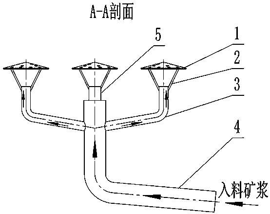
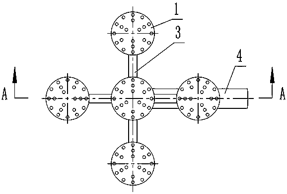
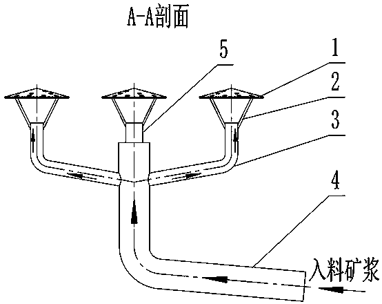
[0018] like figure 1 and figure 2 As shown, the pulp feeding and equalizing device in this embodiment includes a feeding pipe 4 , a branch pipe 3 , an umbrella cap 1 , an umbrella cap support 2 and a central discharge pipe 5 . The feeding pipe 4 is a steel pipe with a large diameter, and the branch pipe 3 is a steel pipe with a thin diameter. Arrangement, the outlet of the branch pipe 3 is on the same horizontal plane and the outlet is kept upward. The umbrella cap 1 adopts an umbrella-shaped structure surrounded by steel plates to form a certain cone angle. Several through holes are evenly distributed on the surface of the umbrella cap. The umbrella cap is connected to the branch pipe 3 through the umbrella cap support 2. The top of the vertical pipe section of the feeding pipe 4 is p...


PUM


Abstract

The invention discloses an inlet ore pulp uniform distribution device. The inlet ore pulp uniform distribution device is composed of a material inlet pipe, branch pipes, umbrella caps, umbrella cap supports and a center material outlet pipe. The material inlet pipe is a steel pipe with a large diameter. The branch pipes are steel pipes with small diameters. The branch pipes communicate with the material inlet pipe. The branch pipes are the same in structure. The number of the branch pipes is at least two. The branch pipes are arranged with the vertical section of the material inlet pipe as thecenter. Outlets of the branch pipes are located on the same horizontal plane and are kept upward. Each umbrella cap is an umbrella-shaped structure defined by a steel plate and is with a certain taper angle. A plurality of through holes are evenly distributed in the surface of each umbrella cap. Each umbrella cap is connected with the corresponding branch pipe through the corresponding umbrella cap support. The center material outlet pipe and one umbrella cap are arranged on the top of the vertical pipe section of the material inlet pipe. The horizontal height of an outlet of the center material outlet pipe coincides with the heights of the corresponding positions of the outlets of the branch pipes. The horizontal height of the umbrella cap of the center material outlet pipe coincides with the heights of the corresponding positions of the umbrella caps of the branch pipes. The inlet ore pulp uniform distribution device is simple in structure, and convenient to make and install; and with the inlet ore pulp uniform distribution device, ore pulp can enter equipment through a pipeline, the purpose of uniform distribution is achieved, the stability of an ore pulp flow field in the equipment is improved, and the sorting accuracy and the sorting efficiency are improved.

Description

technical field [0001] The invention belongs to the technical field of mineral processing equipment, and in particular relates to an ore pulp feeding and evenly distributing device. Background technique [0002] For mineral processing equipment that uses a certain concentration of pulp as the feed material, the pulp needs to be introduced into the equipment through the feed pipe, such as coarse coal slime separators (TCS, TBS). The effect of material dispersion, but this feeding method has the phenomenon of uneven feeding or slow feeding in the pipeline, which leads to uneven distribution of particle size and concentration in the center area and edge area of ​​the equipment , resulting in interference between the product material layer and the sedimentation material layer, and a stable slurry flow state cannot be formed inside, which increases the difficulty of system operation and reduces the separation accuracy and efficiency. Contents of the invention [0003] The tech...

Claims


Application Information

Patent Timeline
Patent Type & Authority Patents(China)
IPC IPC(8): B03B11/00
CPCB03B11/00
Inventor 李太友陈建东王慧锋
Owner TIANJIN MEITENG TECH CO LTD
Learn More