Unlock instant, AI-driven research and patent intelligence for your innovation.
A coupling objective lens for confocal microendoscope
What is Al technical title?
Al technical title is built by PatSnap Al team. It summarizes the technical point description of the patent document.
A technology of confocal microscopy and coupled objects, applied in the field of coupled objective lenses
Active Publication Date: 2021-08-03
JINGWEI SHIDA MEDICAL TECH WUHAN CO LTD
View PDF3 Cites 0 Cited by
Summary
Abstract
Description
Claims
Application Information
AI Technical Summary
This helps you quickly interpret patents by identifying the three key elements:
Problems solved by technology
Method used
Benefits of technology
Problems solved by technology
[0005] Therefore, it is a problem to be solved to design a coupling objective lens that can aim at excitation light and fluorescence achromatism, large working distance, matching numerical aperture and optical fiber bundle numerical aperture, and good coupling performance.
Method used
Image
Click on the blue label to locate the original text in one second.
Reading with bidirectional positioning of images and text.
Examples
Embodiment 1
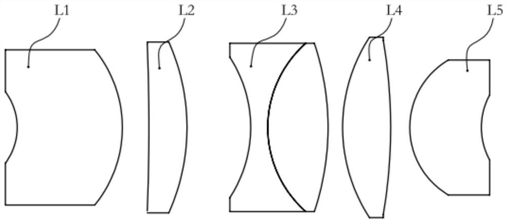
[0017] Such as figure 1 As shown, this embodiment provides a coupling objective lens for a confocal microendoscope, including a first lens L1 with a negative refractive power, a second lens L2 with a positive refractive power, and a third lens with a negative refractive power. Lens L3, a fourth lens L4 with positive refractive power, and a fifth lens L5 with positive refractive power. The light passes through the first lens L1 , the second lens L2 , the third lens L3 , the fourth lens L4 , and the fifth lens L5 in sequence, and finally forms an image on the image plane.
[0018] Further, the first lens L1, the second lens L2, the third lens L3, the fourth lens L4, and the fifth lens L5 are all spherical lenses. Specifically, the third lens is a doublet lens consisting of a biconcave lens and a biconvex lens. This structure is more convenient for processing and simplifies the manufacturing process. The specific parameters of each lens are shown in Table 1.
[0019] Table 1 ...
Embodiment 2
[0032] The lens structure in this embodiment is the same as that in Embodiment 1, the difference is the specific parameters of each lens, see Table 2 for details.
[0033] Table 2 Specific parameters of the coupled objective lens of the confocal microendoscope (unit: mm)
[0034]
[0035] Wherein, the radius of curvature of the front surface of the first lens L1 is -8.389 mm, the radius of curvature of the rear surface is -16.130 mm, the central thickness T1 of the first lens is 14.591 mm, the rear surface of the first lens and the front surface of the second lens The central thickness of the surface is 2.939mm, the material of the first lens is H-ZLAF50D, the clear aperture of the front surface of the first lens is 5mm, and the clear aperture of the rear surface is 10.60mm;
[0036] The radius of curvature of the front surface of the second lens L2 is 93.760 mm, the radius of curvature of the rear surface is -34.051 mm, the central thickness T2 of the second lens is 6.237 ...
PUM
Property
Measurement
Unit
thickness
aaaaa
aaaaa
thickness
aaaaa
aaaaa
pore size
aaaaa
aaaaa
Abstract
The invention provides a coupling objective lens for a confocal microendoscope, comprising a first lens with a negative refractive power, a second lens with a positive refractive power, a third lens with a negative refractive power, and a lens with a positive refractive power. The fourth lens and the fifth lens with positive refractive power are sequentially arranged along the optical axis from the object side to the image side. The coupling objective lens strictly controls the incident and exit angles of the light through the cooperation between the lenses, achromatizes the excitation light and the fluorescencesignal, and makes the numerical aperture match the numerical aperture of the fiber bundle while ensuring a large working distance.
Description
technical field [0001] The invention relates to the technical field of a probe typeconfocalendoscope, in particular to a coupling objective lens for a confocal microendoscope. Background technique [0002] The probe-type confocal microendoscope is composed of two subsystems: the confocal host and the confocal probe. The former provides the functions of optical drive and partial fluorescencesignal collection, and the latter transmits the optical drive coupled from the former, while collecting in a flexible way. fluorescent signal. The interaction between these two subsystems is through the coupled objective lens. Because the coupling objective acts as a bridge between the past and the future, the performance of the coupling objective and the matching of the optical parameters of the entire system are very important. [0003] In order to adapt to the observation of biological specimens and the conversion between objective lenses, various standard documents, such as "GB / T ...
Claims
Application Information
Patent Timeline
Application Date:The date an application was filed.
Publication Date:The date a patent or application was officially published.
First Publication Date:The earliest publication date of a patent with the same application number.
Issue Date:Publication date of the patent grant document.
PCT Entry Date:The Entry date of PCT National Phase.
Estimated Expiry Date:The statutory expiry date of a patent right according to the Patent Law, and it is the longest term of protection that the patent right can achieve without the termination of the patent right due to other reasons(Term extension factor has been taken into account ).
Invalid Date:Actual expiry date is based on effective date or publication date of legal transaction data of invalid patent.
