A Low-rcs Array Antenna with Reconfigurable Scattered Beams

An array antenna and beam technology, which is applied to separately powered antenna arrays, antennas, antenna arrays, etc., can solve problems such as the inability to achieve RCS reduction and the inability to achieve active control of scattered beam beams, and achieve radar cross section reduction, stable radiation characteristics, Overcome the effect of lower antenna gain

Active Publication Date: 2021-09-28
XIDIAN UNIV
View PDF11 Cites 0 Cited by
  • Summary
  • Abstract
  • Description
  • Claims
  • Application Information

AI Technical Summary

Problems solved by technology

The array antenna has the characteristics of stable radiation characteristics and low radar cross-section, but it cannot realize the active control of the scattered wave beam, nor can it realize the reduction of RCS in the case of oblique incidence of electromagnetic waves

Method used


Image

  • A Low-rcs Array Antenna with Reconfigurable Scattered Beams
  • A Low-rcs Array Antenna with Reconfigurable Scattered Beams
  • A Low-rcs Array Antenna with Reconfigurable Scattered Beams

Examples


Embodiment 1

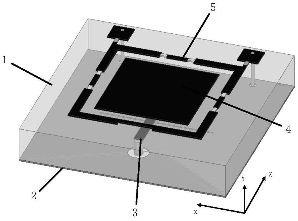
[0029] refer to figure 1 , figure 2 , image 3 ,and Figure 4 ,

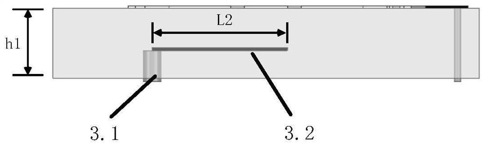
[0030] A low RCS array antenna with reconfigurable scattered beams, comprising a dielectric substrate 1, N slotted metal floors 2 printed on the lower surface of the dielectric substrate 1, N feeding structures 3, and N radiation stickers printed on the upper surface sheet 4 and N annular radiators 5, wherein, N≥2, N is a positive integer; the slotted metal floor 2 is etched with a rectangular slit 2.1; the feed structure 3 is composed of a metal column 3.1 and a rectangular metal sheet 3.2 Composition, the metal column 3.1 runs through the dielectric substrate (1) and is connected to the slotted metal floor 2, and the rectangular metal sheet 3.2 is embedded in the dielectric substrate 1; it is characterized in that:

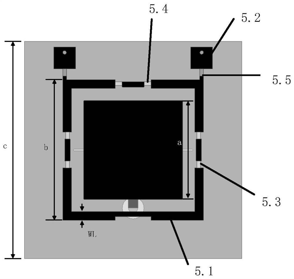
[0031] The annular radiator 5 is composed of a rectangular metal ring 5.1, a metal patch 5.2, a PIN tube 5.3 embedded in the rectangular metal ring 5.1, a capacitor 5.4 and an inductor 5.5; t...

Embodiment 2

[0044] This embodiment has the same structure as Embodiment 1, only the following parameters are adjusted:

[0045] Rectangular metal ring 5.1 is a square ring structure, the outer side length is expressed as b, the width is expressed as WL, the outer side length b is 9mm, and WL is 0.1mm. The radiation patch 4 is a square structure, the side length is expressed as a, and the side length is a is 8mm.

Embodiment 3

[0047] refer to figure 2

[0048] Rectangular metal ring 5.1 is a square ring structure, the outer side length is expressed as b, the width is expressed as WL, the outer side length b is 31mm, and the width WL is 2.1mm. The radiation patch 4 is a square structure, the side length is expressed as a, and the side length a is 26mm.

[0049] Below in conjunction with accompanying drawing and the present invention will be further described

[0050] 1. Simulation content and conditions

[0051] Utilize commercial simulation software Ansoft HFSS to carry out simulation calculation to the radiation pattern of above-mentioned embodiment at 5GHZ place, the result is as follows Figure 5 shown.

[0052] Utilize commercial simulation software Ansoft HFSS to carry out simulation calculation to the monostatic radar cross section of above-mentioned embodiment, the result is as follows Figure 6 shown, where: Figure 6 (a) is a comparison diagram of the radar cross section of a single ...


PUM


Abstract

The present invention proposes a low RCS array antenna with reconfigurable scattered beams, including a dielectric substrate, N slotted metal floors printed on the lower surface of the dielectric substrate, N feeding structures, and N radiation stickers printed on the upper surface. sheet and N ring radiators, the feed structure is composed of metal columns and rectangular metal sheets, and the ring radiator is composed of rectangular metal rings, metal patches and PIN tubes embedded in the rectangular metal rings, capacitors and inductors ; The rectangular metal ring is provided with M×N openings, wherein M≥1, and the ends of the openings are respectively connected to the PIN tube and the capacitor; the metal patch is located outside the rectangular metal ring, and is connected to the rectangular metal ring through an inductor The metal rings are connected; the invention adjusts the scattered wave beam through the rectangular radiation ring, and obtains the effect of high gain under the condition of ensuring the radiation characteristics of the antenna array, and realizes the obvious reduction of the radar scattering cross section under the vertical incidence and oblique incidence of the antenna.

Description

technical field [0001] The invention belongs to the technical field of antennas, and in particular relates to a low-RCS array antenna with reconfigurable scattered beams, which is applicable to communication antennas and missile antennas with low observable characteristics. Background technique [0002] In the traditional communication field, the signal transmitting and receiving system is one of the most important components of the entire communication platform, the antenna is the core part of the system, and the radiation characteristics of the antenna are the main indicators to measure the quality of the antenna. As antennas are increasingly used in military fields such as aircraft, missiles, and ships, people's requirements for antenna scattering characteristics are also getting higher and higher. The key to improving the antenna scattering characteristics is how to reduce the radar cross section, and the radar cross section is the most basic parameter in the scattering ...

Claims


Application Information

Patent Timeline
Patent Type & Authority Patents(China)
IPC IPC(8): H01Q1/38H01Q1/48H01Q1/50H01Q3/44H01Q21/06
CPCH01Q1/38H01Q1/48H01Q1/50H01Q3/44H01Q21/065
Inventor 贾永涛张家豪刘英
Owner XIDIAN UNIV
Why Eureka
Try Eureka