
LED drive circuit and drive device

An LED driving and circuit technology, applied in the application of electrical components and semiconductor lamps, etc., can solve the problems of damage to the resistance Rb and the first constant current source SC1, abnormal operation, abnormal operation of the LED driving circuit, etc., so as to improve the anti-surge. ability, the effect of ensuring safety

Pending Publication Date: 2020-03-27
SHENZHEN SHENDIE SEMICON
View PDF0 Cites 2 Cited by
  • Summary
  • Abstract
  • Description
  • Claims
  • Application Information

AI Technical Summary

Problems solved by technology

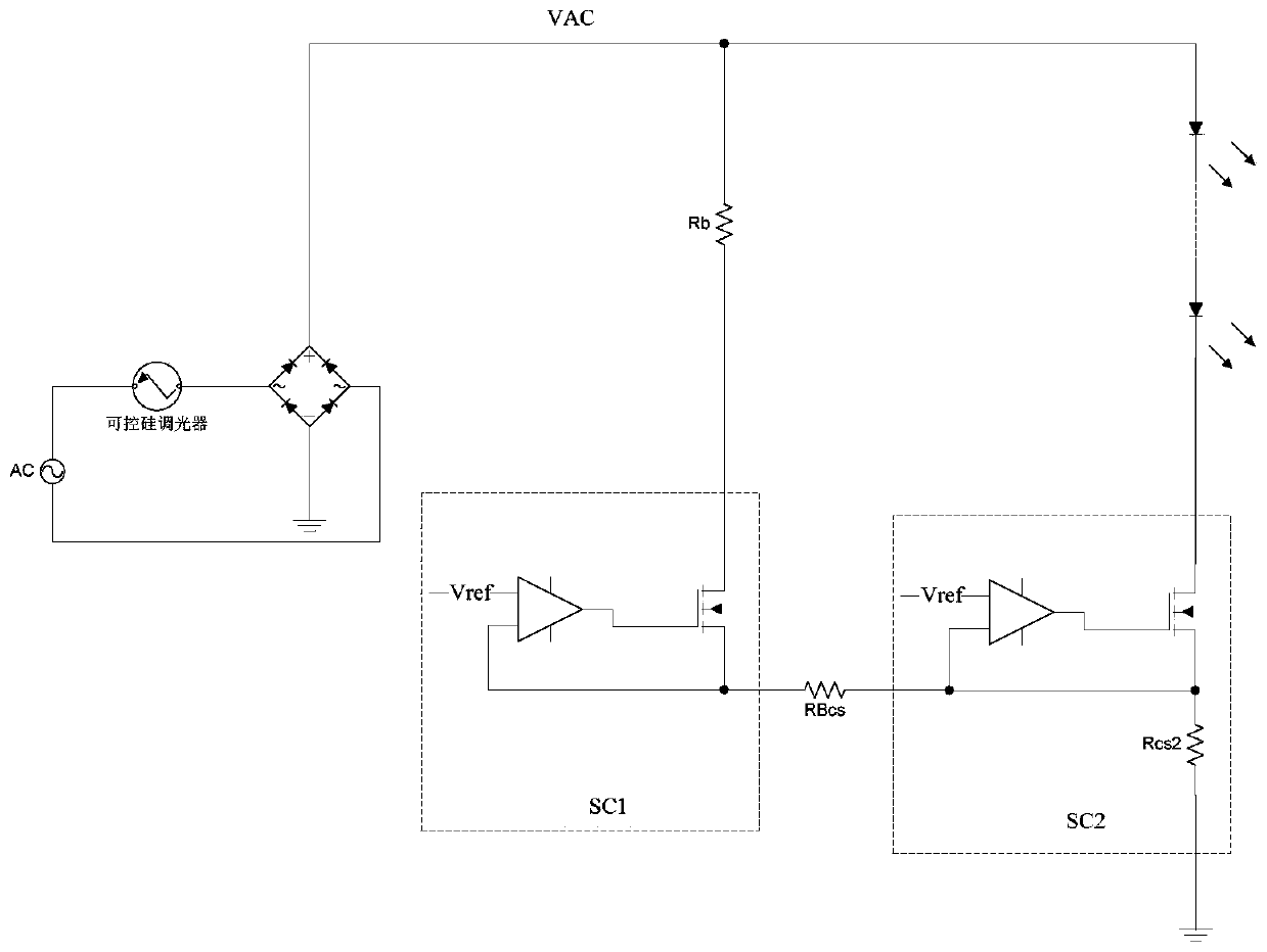
[0002] like figure 1 As shown, in the existing LED drive circuit using thyristor dimming, when the phase of the thyristor dimmer is cut, a discharge current is required, otherwise it will cause abnormal operation
And when the online voltage of the LED lamp is lower than the lighting voltage of the LED lamp, the LED lamp has no current flow, so the LED drive circuit compatible with the thyristor dimmer will add an additional discharge circuit
However, since the discharge current does not flow through the light string, but only flows through the resistor Rb and the first constant current source SC1, when a high voltage surge occurs in the power supply network, the surge high voltage is borne by the resistor Rb and the first constant current source SC1 , it is easy to cause damage to the resistor Rb and the first constant current source SC1, resulting in abnormal operation of the LED drive circuit

Method used


Image

  • LED drive circuit and drive device
  • LED drive circuit and drive device
  • LED drive circuit and drive device

Examples


Embodiment Construction

[0022] The object of the present invention is to provide an LED driving circuit and a driving device, which can effectively improve the anti-surge capability and ensure the safety of the LED driving circuit.

[0023] In order to make the object, technical solution and effect of the present invention more clear and definite, the present invention will be further described in detail below with reference to the accompanying drawings and examples. It should be understood that the specific embodiments described here are only used to explain the present invention, not to limit the present invention.

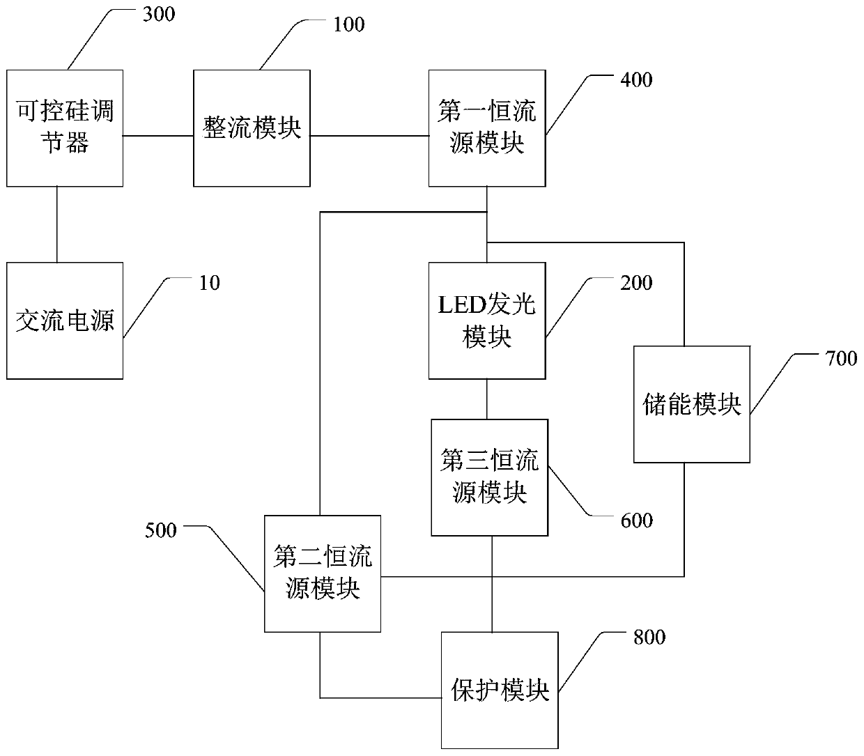
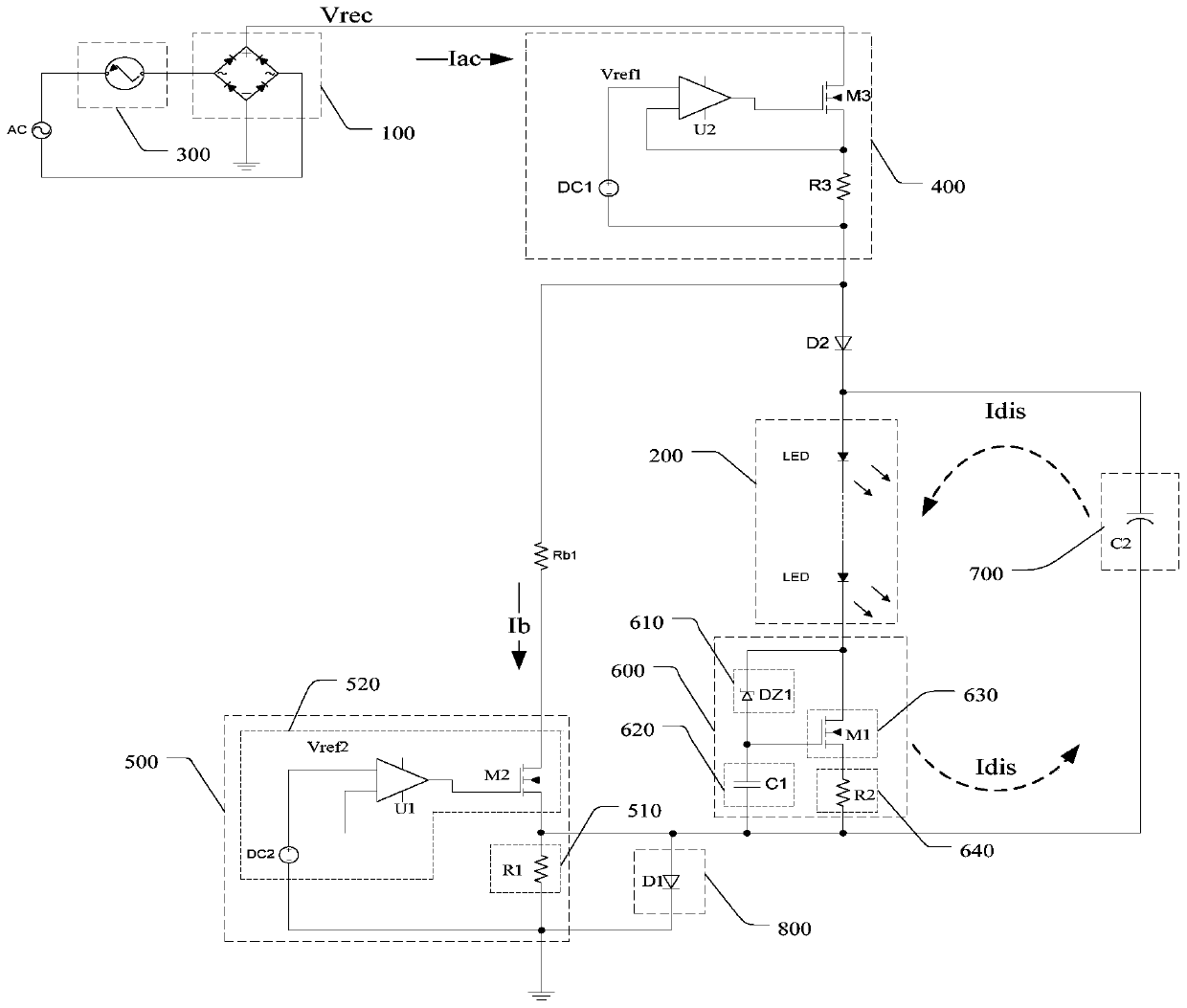
[0024] see figure 2 , the LED driving circuit provided by the present invention includes a rectifier module 100, an LED lighting module 200, a thyristor regulator 300 for adjusting the brightness of the LED lighting module 200, a first constant current source module 400, and a second constant current source module 500 , the third constant current source module 600, the energy storage...


PUM


Abstract

The invention discloses an LED drive circuit and a drive device. The LED drive circuit comprises an LED light-emitting module, a silicon controlled rectifier regulator used for regulating the brightness of the LED light-emitting module, a first constant current source module, a second constant current source module, a third constant current source module, an energy storage module and a protectionmodule, wherein the first constant current source module is used for providing drive current for the LED light-emitting module; the second constant current source module is used for providing discharge current for the silicon controlled rectifier adjusting module and maintaining current for maintaining conduction of the silicon controlled rectifier adjusting module when the on-line voltage is smaller than the conduction voltage of the LED light emitting module; the energy storage module is used for supplying power to the LED light-emitting module when the on-line voltage is smaller than the conduction voltage of the LED light-emitting module; the third constant current source module is used for adjusting the output current of the LED light-emitting module; according to the LED drive circuit, the anti-surge capacity can be effectively improved, and the working safety of the LED drive circuit is guaranteed.

Description

technical field [0001] The invention relates to the technical field of LEDs, in particular to an LED driving circuit and a driving device. Background technique [0002] Such as figure 1 As shown, in the existing LED driver circuit using thyristor dimming, when the phase of the thyristor dimmer is cut, a discharge current is required, otherwise it will cause abnormal operation. However, when the online voltage of the LED lamp is lower than the lighting voltage of the LED lamp, no current flows through the LED lamp. Therefore, an additional discharge circuit is added to the LED drive circuit compatible with the thyristor dimmer. However, since the discharge current does not flow through the light string, but only flows through the resistor Rb and the first constant current source SC1, when a high voltage surge occurs in the power supply network, the surge high voltage is borne by the resistor Rb and the first constant current source SC1 , it is easy to cause damage to the re...

Claims


Application Information

Patent Timeline
Patent Type & Authority Applications(China)
IPC IPC(8): H05B45/10H05B45/345
CPCY02B20/30
Inventor 麦炎全陈博邓迅升
Owner SHENZHEN SHENDIE SEMICON
Learn More