
Mould capable of demoulding keycap through short oblique pins

A keycap and demoulding technology, which is applied in the mold field of short oblique pin demoulding keycaps, can solve the problems of damaging the keycap, affecting the finished product of the mold, and affecting the ejection of the keycap, so as to achieve the effect of increasing the straight line and reducing waste products

Pending Publication Date: 2020-03-31
苏州亿源精密模具有限公司
View PDF4 Cites 4 Cited by
  • Summary
  • Abstract
  • Description
  • Claims
  • Application Information

AI Technical Summary

Problems solved by technology

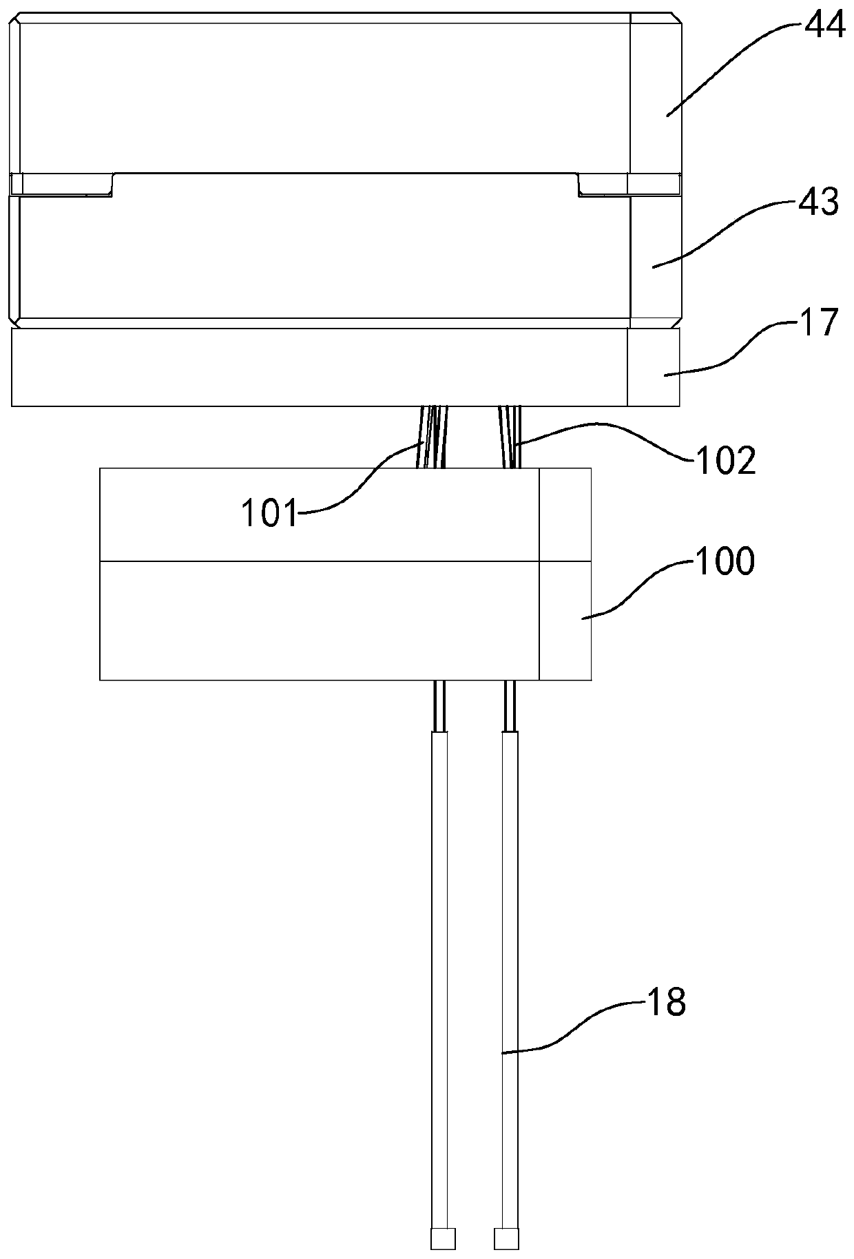
[0004] The above-mentioned existing technical solutions have the following defects: when taking out the formed keycap mold in the injection mold, it is necessary to drive the ejector rod to move towards the fixed mold with the material taking block, and use the ejector rod to drive the direct pin on the ejector rod to move the key in the mold. The cap is ejected, but because the length of the direct pin and the thimble is too long, the straightness of the pick-up block is not enough when driving the thimble to move, which will affect the ejection of the keycap. The deviation of the straight line will cause the direction of the direct pin to change, so that the When the keycap is pushed out, the keycap is damaged, which will eventually affect the finished product of the mold

Method used


Image

  • Mould capable of demoulding keycap through short oblique pins
  • Mould capable of demoulding keycap through short oblique pins
  • Mould capable of demoulding keycap through short oblique pins

Examples


Embodiment

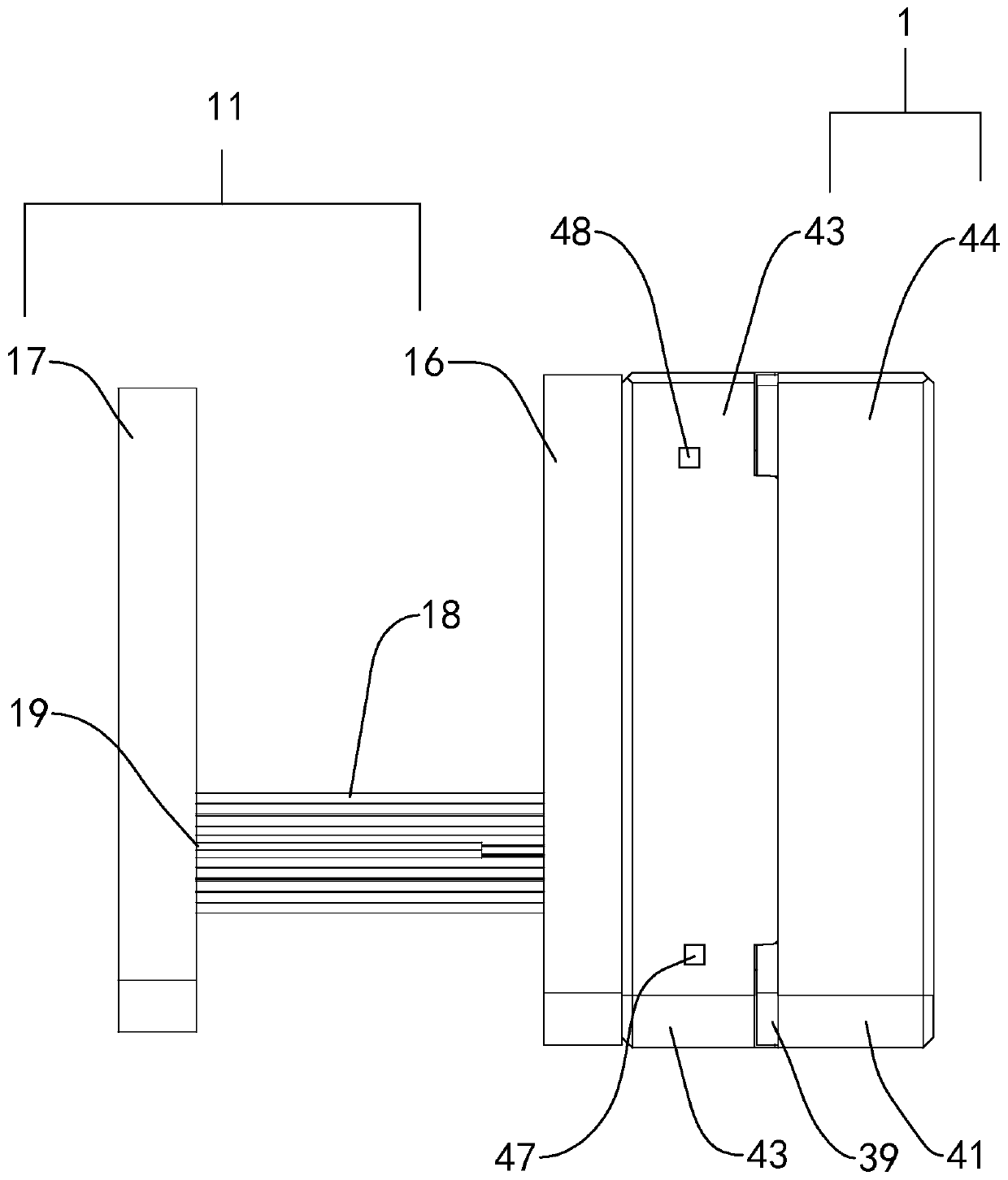
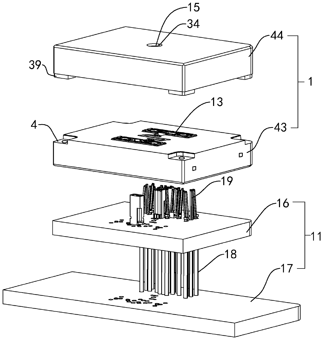
[0048] refer to figure 2 , a mold for demoulding keycaps with short oblique pins disclosed in the present invention, comprising an injection molding assembly 1 and a jacking assembly 11, the injection molding assembly 1 includes a fixed mold 44 and a moving mold 43 for forming a keycap, and the jacking assembly 11 includes Close to the top plate 16 of the movable mold 43 and the bottom plate 17 away from the top plate 16, the bottom plate 17 is provided with a plurality of ejector rods 18 and resisting rods 19 fixed on the bottom plate 17. The function of the ejector rods 18 and the resisting rods 19 is to help Keycap molding and automatic return of formed keycaps.

[0049] refer to image 3 and Figure 4 The upper molding cavity 12 is provided on the opposite surface of the fixed mold 44 and the movable mold 43, and the lower molding cavity 13 corresponding to the upper molding cavity 12 is provided on the movable mold 43. After the movable mold 43 and the fixed mold 44 ov...


PUM


Abstract

The invention relates to a mould capable of demoulding a keycap through short oblique pins. The mould capable of demoulding the keycap through the short oblique pins comprises an injection molding assembly and an ejection assembly, wherein the injection molding assembly comprises a fixed die and a movable die; the butt-joint surfaces of the movable die and the fixed die form a keycap forming cavity; an injection molding inlet communicating with the keycap forming cavity is formed in the fixed die; the ejection assembly comprises a top plate and a bottom plate clinging to the movable die; multiple ejection rods and support rods fixed onto the bottom plate are arranged on the bottom plate; multiple fixed holes for the ejection rods and the support rods to penetrate through are formed in theejection rods; the short oblique pins clamped with the ejection rods are arranged on the ejection rods; grooves clamped with the ejection rods are arranged on the short oblique pins; semi-cylindricalclips clamped into back grooves are arranged on the ejection rods; cylindrical bulges are arranged on one sides, far away from the grooves, on the short oblique pins; and support holes for placing thesupport rods are further formed in the movable die. The mould capable of demoulding the keycap through the short oblique pins provided by the invention has the effects that through reducing the lengths of the short oblique pins on the ejection rods, the linearity when the short oblique pins are pushed by the bottom plate is increased, and the yield of the keycap is further ensured.

Description

technical field [0001] The invention relates to the technical field of keycap molds, in particular to a mold for demoulding keycaps with short oblique pins. Background technique [0002] There are many types of keyboards, and different types of key caps should be installed on different types of keyboards. After molding in the cavity, demoulding is required. [0003] refer to figure 1 , figure 1 In is a kind of mold of existing keycap injection molding, comprises injection mold, and described injection mold comprises movable mold 43 and fixed mold 44, and described movable mold 43 and fixed mold 44 are provided with for keycap injection molding. Die cavity, the side of the movable mold 43 away from the fixed mold 44 is provided with a bottom plate 17 close to the movable mold 43, the bottom plate 17 is inserted with a direct pin 102 and a thimble 101 that are in contact with the movable mold 43, and the side of the bottom plate 17 is There is a take-up block 100 for pushi...

Claims


Application Information

Patent Timeline
IPC IPC(8): B29C45/26B29C45/40B29C45/73
CPCB29C45/26B29C45/4005B29C45/7312
Inventor 叶元革
Owner 苏州亿源精密模具有限公司
Learn More