
Cable winding device for electric power construction

A winding device and electric power construction technology, applied in the field of electric power, can solve problems such as low winding quality and loose cables, and achieve the effect of improving winding quality and increasing winding volume

Active Publication Date: 2021-07-13
PINGDINGSHAN POWER SUPPLY ELECTRIC POWER OF HENAN
View PDF10 Cites 0 Cited by
  • Summary
  • Abstract
  • Description
  • Claims
  • Application Information

AI Technical Summary

Problems solved by technology

[0002] In the process of electric power construction, the cable needs to be reeled. The traditional cable reeling device only relies on the rotating reel to reel. During the reeling process, the cables are loose and the reeling quality is not high.

Method used


Image

  • Cable winding device for electric power construction
  • Cable winding device for electric power construction
  • Cable winding device for electric power construction

Examples


Embodiment 1

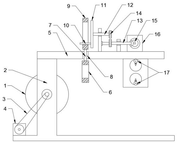
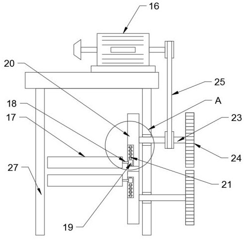
[0022] see Figure 1-5 , in an embodiment of the present invention, a cable winding device for electric power construction, including a winding reel 1 and a mounting seat 2; A winding motor 4 is connected, and the winding motor 4 is fixedly connected with the mounting base 2; the winding drum 1 is driven to rotate by the winding motor 4, and the cable is wound.

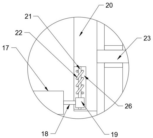
[0023] The front end of the reel 1 is provided with an elastic traction mechanism. The traction mechanism includes a set of traction rollers 17 arranged up and down oppositely. A set of traction rollers 17 are respectively connected to slide blocks 19 through rotating shafts 18, and slide blocks 19 are nested with turntables. 20, the turntable 20 is provided with a radial groove 26, the slider 19 is nested in the radial groove 26 and is slidably connected with the radial groove 26; the radial groove 26 is provided with a guide rod 21, and the guide rod 21 runs through the slider 19 and is slidably connected with the ...

Embodiment 2

[0026] The difference between this embodiment and Embodiment 1 is that a guiding mechanism is provided between the reel 1 and the elastic traction mechanism. The guiding mechanism includes a guiding ring 6 and a longitudinal reciprocating mechanism. Sliding bar 7, top plate 5 is provided with longitudinal chute 8, and sliding bar 7 runs through longitudinal chute 8 and is slidably connected with longitudinal chute 8; The upper end of described sliding bar 7 is fixed with vertically arranged rectangular frame 9, rectangular frame 9 An eccentric column 10 is nested inside, and the eccentric column 10 is fixedly connected with an eccentric disc 11, and the eccentric disc 11 is fixedly connected with a support shaft 12, and the support shaft 12 is rotatably connected with a mounting plate, and the mounting plate is fixedly connected with the top plate 5; the support shaft 12 The transmission shaft 13 is connected with the transmission belt 14, and the transmission shaft 13 is conne...


PUM


Abstract

The invention discloses a cable winding device for electric power construction, which includes a winding drum and a mounting seat; the front end of the winding drum is provided with an elastic traction mechanism, and the traction mechanism includes a group of traction rollers arranged up and down oppositely, and the traction rollers respectively pass through The rotating shaft is rotatably connected with a slider, the slider is nested with a turntable, and the turntable is provided with a radial groove; the radial groove is provided with a guide rod that runs through the slider and is slidably connected with the slider. Spring on the guide rod. The invention realizes the elastic pulling of the cable opposite to the coiling direction by being provided with a turntable that can rotate in opposite directions, a traction roller, a slider, a guide rod, and a spring, so that the cable is kept in a tensioned state, and the coil is kept tight, improving Winding quality: through the installation of a guide ring and a longitudinal reciprocating mechanism including a sliding rod, a rectangular frame, an eccentric column, and an eccentric disc, the longitudinal reciprocating movement of the guide ring is realized, so that the cable is evenly wound on the reel, and the winding speed is improved. quantity and winding quality.

Description

technical field [0001] The invention relates to the field of electric power, in particular to a cable winding device for electric power construction. Background technique [0002] In the process of electric power construction, it is necessary to rewind the cables. The traditional cable rewinding device only relies on the rotating reel to rewind. During the rewinding process, the cables are loose and the rewinding quality is not high. [0003] The present application provides a cable winding device for electric power construction, which realizes tight winding of cables. Contents of the invention [0004] The object of the present invention is to provide a cable winding device for electric power construction, so as to solve the problems raised in the above-mentioned background technology. [0005] To achieve the above object, the present invention provides the following technical solutions: [0006] A cable winding device for electric power construction, including a windin...

Claims


Application Information

Patent Timeline
Patent Type & Authority Patents(China)
IPC IPC(8): B65H54/28B65H59/10
CPCB65H54/2818B65H59/10B65H2515/31B65H2701/34
Inventor 王冠瑞艾晓雨贾子昊刘林曼李肖可李晓航刘智强王得道邱骏靳耀珂雷飒陈运政
Owner PINGDINGSHAN POWER SUPPLY ELECTRIC POWER OF HENAN
Learn More