
Method for determining flow-back model of shale gas fracturing fluid

A fracturing fluid and shale gas well technology, which is applied in the fields of earthwork drilling, measurement, wellbore/well components, etc., can solve the problems that limit the stable production capacity of shale gas wells, cannot diagnose gas well problems, and cannot determine the productivity of fracturing fluids and gas wells. impact, etc.

Active Publication Date: 2020-03-31
CHINA PETROLEUM & CHEM CORP +1
View PDF5 Cites 2 Cited by
  • Summary
  • Abstract
  • Description
  • Claims
  • Application Information

AI Technical Summary

Problems solved by technology

[0006] The purpose of the present invention is to overcome the research methods that have not been found in the prior art to determine the production mechanism of shale gas well fracturing fluid and reflect the influence of fracturing fluid flowback rate on gas well productivity, and cannot diagnose the problems that occur in the production process of gas wells , it is impossible to determine the impact of fracturing fluid production on gas well productivity, which limits the lack of stable production capacity of shale gas wells, and provides a method to determine the flowback model of shale gas fracturing fluid

Method used


Image

  • Method for determining flow-back model of shale gas fracturing fluid
  • Method for determining flow-back model of shale gas fracturing fluid
  • Method for determining flow-back model of shale gas fracturing fluid

Examples


Embodiment Construction

[0027] The present invention will be further described in detail below in conjunction with test examples and specific embodiments. However, it should not be understood that the scope of the above subject matter of the present invention is limited to the following embodiments, and all technologies realized based on the content of the present invention belong to the scope of the present invention.

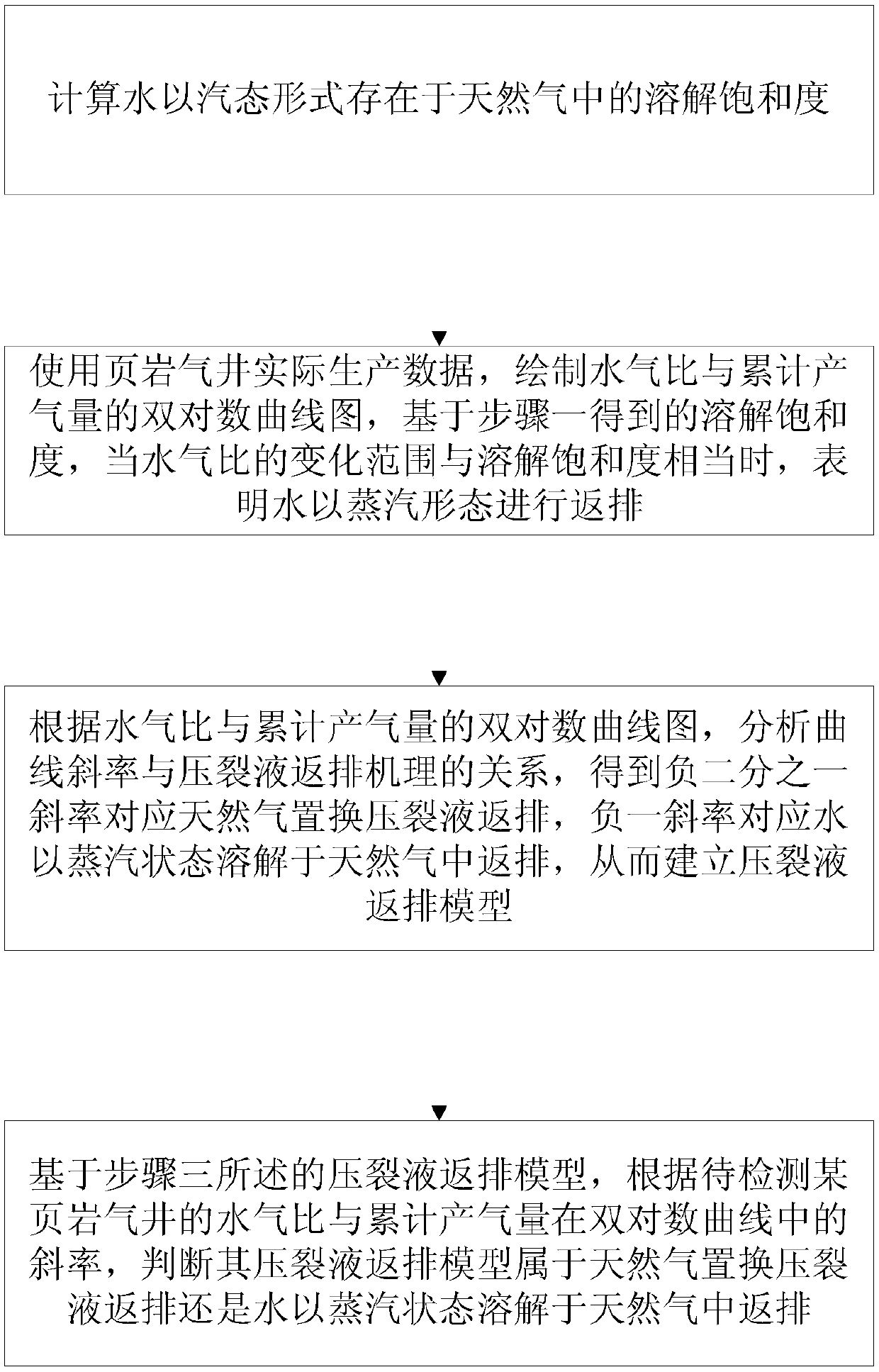
[0028] Such as figure 1 As shown, a method for determining the flowback model of shale gas fracturing fluid includes the following steps:

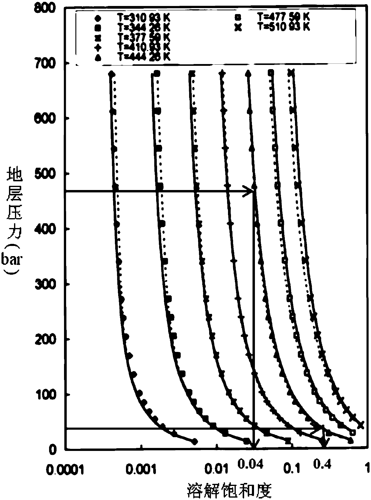
[0029] Step 1: According to formation pressure and temperature, calculate the solubility saturation of water in gaseous form in natural gas. Such as figure 2 As shown, in this example, statistics are made on the Horn River shale gas reservoir, the formation pressure ranges from 313-471bar, the bottomhole flow pressure is 45-70bar, and the formation temperature T=448K, the solution saturation is roughly between 0.04-0.4 between.

[0030] Step...


PUM


Abstract

The invention discloses a method for determining a flow-back model of a shale gas fracturing fluid. The method comprises the steps that a dissolution saturation degree of water existing in natural gasin a steam state is computed; a two-logarithm curve map of water-gas ratios and cumulative gas amounts is drawn according to actual production data of a shale gas well, and when a changing scope of the water-gas ratios is equivalent with the dissolution saturation degree based on the dissolution saturation degree, back flowing of the water in the form of steam can be confirmed; according to the two-logarithm curve map of the water-gas ratios and the cumulative gas amounts, relations between a curve slope and a fracturing fluid flow-back mechanism are obtained, namely the slope of -1 / 2 is corresponding to the back flowing of the fracturing fluid with natural gas replacement, and the slope of -1 is corresponding to dissolution of the water in the natural gas in the steam state for back flowing, so a fracturing fluid flow-back model is established; and based on the fracturing fluid flow-back model and according to a slope of water-gas ratios and cumulative gas accounts of a to-be-detected shale gas well in a two-logarithm curve, whether the fracturing fluid flow-back model belongs to fracturing fluid back flowing with natural gas replacement and dissolution of the water in the natural gas in the steam state for back flowing can be judged.

Description

technical field [0001] The invention relates to the technical field of shale gas reservoir development, in particular to a method for determining a shale gas fracturing fluid flowback model. Background technique [0002] In the past ten years, the staged fracturing technology of horizontal wells has made great success in the development and production of shale gas reservoirs. In the process of hydraulic fracturing, a large amount of fracturing fluid is injected into the formation to form fractures, and the amount of fracturing fluid is 5 to 10 times that of conventional oil and gas reservoirs. According to the data collected at the fracturing site, only a small part of the fracturing fluid flows back to the ground after the fracturing operation, and the flowback rate is usually 10% to 40%. [0003] Studies have shown that the main reasons for the low fracturing fluid flowback rate are poor fracturing fluid flowback effect in man-made fractures, shale wetting, capillary acti...

Claims


Application Information

Patent Timeline
IPC IPC(8): E21B47/00E21B43/267
CPCE21B47/00E21B43/267
Inventor 张燕南刘成川熊亮史洪亮赵勇董晓霞魏力民王岩
Owner CHINA PETROLEUM & CHEM CORP
Learn More