
Threading structure for urban electric power engineering construction

A power engineering and urban technology, applied in cable installation, cable laying equipment, electrical components, etc., can solve the problems of poor wire stability, inconvenient steering, inconvenient storage, etc., and achieve the effect of improving stability and anti-dropping performance.

Active Publication Date: 2020-03-31
天津华烁电力技术开发有限公司
View PDF8 Cites 3 Cited by
  • Summary
  • Abstract
  • Description
  • Claims
  • Application Information

AI Technical Summary

Problems solved by technology

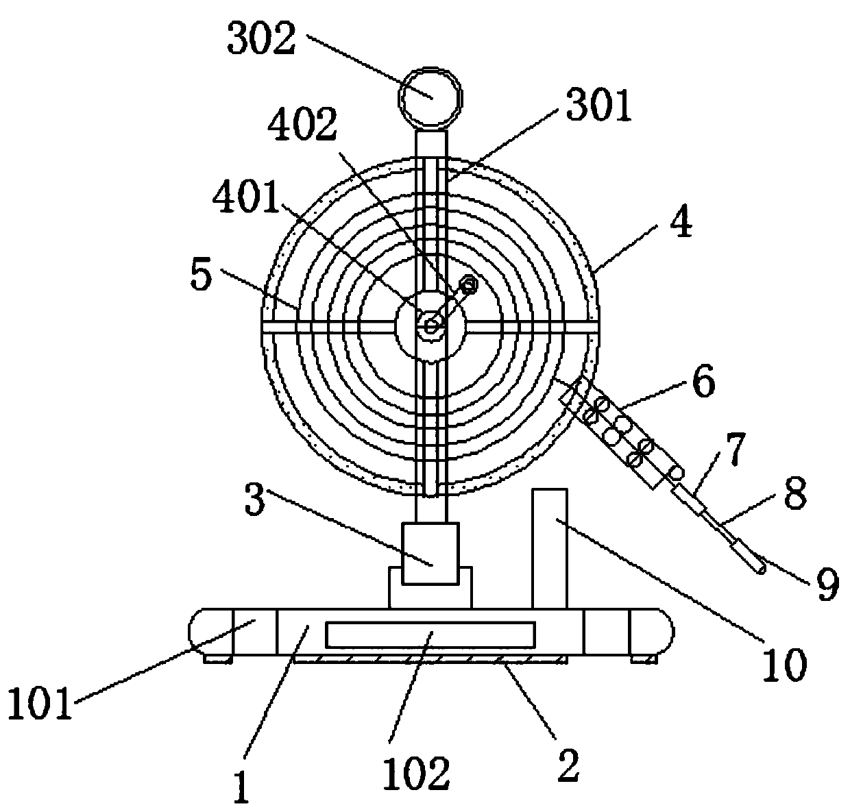
[0010] The purpose of the present invention is to provide a threading structure for urban electric power engineering construction, to solve the problem that the existing threading structure for urban electric power engineering construction in the above-mentioned background technology is in use, and the steel wire is wound inside the winding reel, which is inconvenient Installing and fixing the winding reel will affect the effect of steel wire pay-off; during the process of unwinding, the length of the unwound wire cannot be known in real time, and the progress of the construction time cannot be judged; when the lead head is used to fix the wire, the stability of the wire is poor , easy to fall off, affecting the smooth progress of the construction; the guide head advances in the pipeline, it is inconvenient to turn, and it is worn with the inner wall of the pipeline, which affects the service life of the guide head and the pipeline. After use, the guide head and the guide head are not easy to store.

Method used


Image

  • Threading structure for urban electric power engineering construction
  • Threading structure for urban electric power engineering construction
  • Threading structure for urban electric power engineering construction

Examples


Embodiment Construction

[0034] The following will clearly and completely describe the technical solutions in the embodiments of the present invention with reference to the drawings in the embodiments of the present invention.

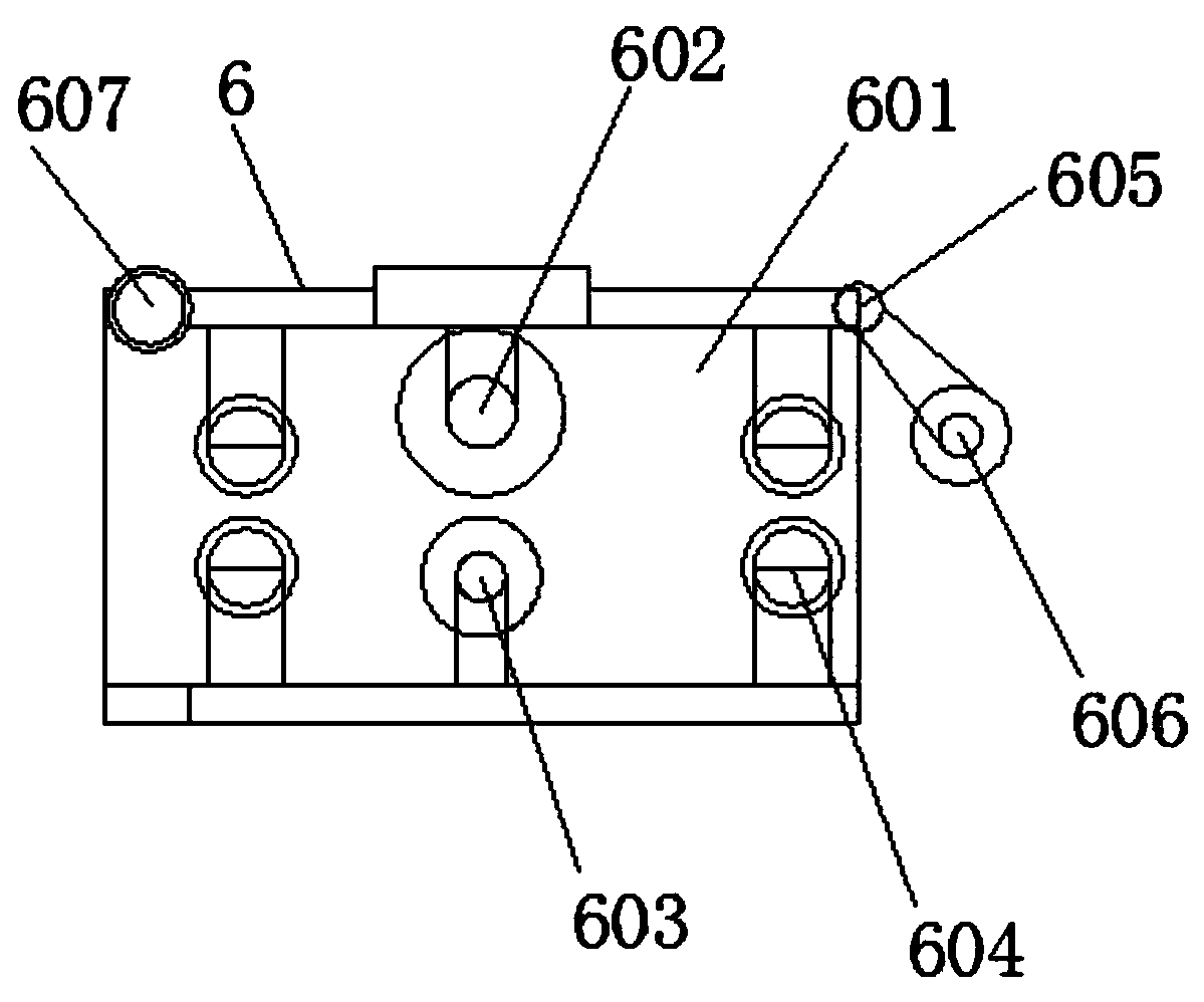
[0035] Such as Figure 1-7 As shown, the present invention provides a technical solution: a threading structure for urban electric power engineering construction, including a base 1, a supporting frame 301 is rotatably connected above the base 1, and a winding reel 4 is fixedly connected inside the supporting frame 301, A steel wire 5 is installed inside the winding reel 4 , one end of the steel wire 5 is fixedly connected to the guide head 9 through a traction head 7 and a spring 8 , and one side of the winding reel 4 is movably connected to the measuring device 6 through a locking wheel 11 .

[0036]The surface of the base 1 is symmetrically provided with threaded holes 101, the side wall of the base 1 is provided with a counterweight groove 102, the lower surface of the bas...


PUM


Abstract

The invention discloses a threading structure for urban electric power engineering construction. The threading structure includes a base, a supporting frame is rotationally connected to the upper portion of the base. The inside of the supporting frame is fixedly connected with a winding disc. A steel wire is mounted in the winding disc; one end of the steel wire is fixedly connected with the guidehead through the traction head and the spring; one side of the winding disc is movably connected with a measuring device through a locking wheel; the design is novel, the base is rotationally connected to the lower portion of the supporting frame outside the winding disc. A lifting ring is welded at the top end of the supporting frame, the winding disc can be conveniently fixed at the initial position of paying off through the base or the lifting ring; the pay-off length is monitored in real time through a distance measuring wheel of the measuring device; a wire groove is formed in the surface of the traction head, so that a wire is conveniently clamped and fixed, the stability is improved, the top end and the two side walls of the guide head are rotationally connected with rollers, the guide head is guided, the pay-off smoothness is improved, abrasion is reduced, and the traction head and the guide head are conveniently stored by arranging a U-shaped clamping plate.

Description

technical field [0001] The invention relates to the technical field of auxiliary equipment for urban electric engineering construction, in particular to a threading structure for urban electric engineering construction. Background technique [0002] Electric power engineering refers to engineering related to the production, transmission, and distribution of electric energy. In a broad sense, it also includes engineering that uses electricity as power and energy in various fields. At the same time, it can be understood that the power transmission and transformation industry expansion project. The production of electric energy mainly relies on thermal power plants, hydropower plants and nuclear power plants. Where conditions permit, tidal, geothermal and wind energies are also used to generate electricity. The transmission and distribution of electric energy is mainly realized through high and low voltage AC power networks. As the development direction of power transmission...

Claims


Application Information

Patent Timeline
Patent Type & Authority Applications(China)
IPC IPC(8): G01B5/02H02G1/08
CPCG01B5/02H02G1/081H02G1/083
Inventor 吴晓杰成林全张荣武
Owner 天津华烁电力技术开发有限公司
Learn More