Heat dissipation and drainage device of fireproof groove box

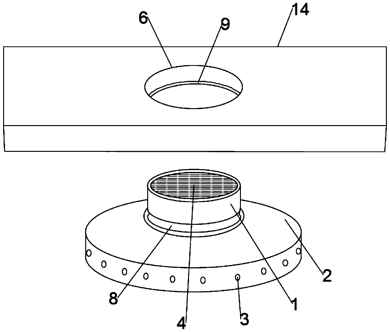
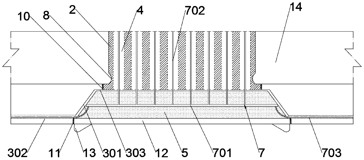
A technology of drainage device and fireproof groove, which is applied to electrical components and other directions, can solve problems such as inability to drain water and isolate fire, and achieve the effects of preventing fire from spreading, shortening heating response time, and simplifying structure.

Pending Publication Date: 2020-03-31
GUANGDONG POWER GRID CO LTD +1
View PDF1 Cites 0 Cited by
  • Summary
  • Abstract
  • Description
  • Claims
  • Application Information

AI Technical Summary

Problems solved by technology

[0004] For this reason, the embodiment of the present invention provides a heat dissipation and drainage device for a fireproof slot box to solve the problems in the prior art that water cannot be drained and fire can not be isolated

Method used


Image

  • Heat dissipation and drainage device of fireproof groove box
  • Heat dissipation and drainage device of fireproof groove box

Examples


Embodiment Construction

[0023] In order to make the purpose, features and advantages of the present invention more obvious and understandable, the technical solutions in the embodiments of the present invention will be clearly and completely described below in conjunction with the accompanying drawings in the embodiments of the present invention. Obviously, the following The described embodiments are only some, not all, embodiments of the present invention. Based on the embodiments of the present invention, all other embodiments obtained by persons of ordinary skill in the art without making creative efforts belong to the protection scope of the present invention.

[0024] The technical solutions of the present invention will be further described below in conjunction with the accompanying drawings and through specific implementation methods.

[0025] In the description of the present invention, it should be understood that the orientations or positional relationships indicated by the terms "upper", "...


PUM


Abstract

The embodiment of the invention discloses a heat dissipation and drainage device of a fireproof groove box, wherein the mounting hole is formed in the lower bottom surface of the fireproof groove boxalong the gravity direction; a first part is clamped in the mounting hole; wherein the first component is detachably connected with a second component, the first component is provided with a dual-purpose barrier which is through along the gravity direction, the second component is internally provided with a dual-purpose channel, the dual-purpose channel is internally provided with an expansion material core which is used for being heated to expand so as to block the dual-purpose channel, and the dual-purpose channel is communicated with the outside and the dual-purpose barrier. According to the invention, the first part, the second part and the expansion material core are arranged; the expansion material core is arranged in the fireproof groove box, so that the device has the effect of isolating the fire behavior between the interior of the fireproof groove box and the outside while giving consideration to air permeability and water drainage, the thermal response time of the expansionmaterial core is shortened, fire spreading and expanding can be prevented, the structure of the device can be simplified through multi-purpose development of a dual-purpose barrier and a dual-purposechannel structure, and the production cost is reduced.

Description

technical field [0001] The embodiment of the present invention relates to the technical field of cable trough boxes, and in particular to a heat dissipation and drainage device for a fireproof trough box. Background technique [0002] Cable tray boxes are usually made of high temperature and fire resistant materials. As a common support and protection device for cable laying in the power supply system of electrical equipment, the cable trough box plays a role in protecting and guiding the cables laid in the cable trough box. However, in actual use, a large amount of heat energy will be generated due to the operation of the cable, and the cable box is usually a sealed structure, so that the heat cannot be dissipated to the outside. The cable catches fire. [0003] In the prior art, air-permeable cable troughs are usually used to solve the above problems. For example, the utility model with application number CN201621114231.6 provides louver-shaped ventilation holes on the t...

Claims


Application Information

Patent Timeline
Patent Type & Authority Applications(China)
IPC IPC(8): H02G3/04
CPCH02G3/0406H02G3/0412
Inventor 卢润波陈志明吴俊黄国尊
Owner GUANGDONG POWER GRID CO LTD
Why Eureka
Try Eureka