Wiring circuit of wall fan motor

A technology for wiring circuits and wall fans, which is used in emergency protection circuit devices, control of multiple AC motors, electrical components, etc. Productivity, saving wire sheathing effect

Active Publication Date: 2020-03-31
佛山市深茂科技有限公司
View PDF9 Cites 0 Cited by
  • Summary
  • Abstract
  • Description
  • Claims
  • Application Information

AI Technical Summary

Problems solved by technology

[0003] In actual production, such as figure 1 As shown, the circuit part of the steering wall fan is mainly composed of a synchronous motor 3 for steering, a capacitive motor 2 for driving the blades to rotate, a multi-speed speed control switch 1, a control switch 5, and a power connector 6. The multi-speed speed control switch is operated to realize the working state of the capacitive motor, and then control the wind speed. The working state of the synchronous motor is controlled by controlling the opening and closing of the switch, and then the steering of the wall fan is controlled. Since the capacitive motor is easier to damage than the synchronous motor, When designing the circuit, a thermal fuse is used to protect the capacitive motor. The secondary winding 8 of the capacitive motor 2 is connected to the multi-speed static switching contacts of the multi-speed speed control switch 1 in sequence through the first wire. The thermal fuse of the capacitive motor 2 The output end of the fuse 9 is connected to the closing terminal 4 through the second electric wire, and the two ends of the synchronous motor 3 are respectively connected to the control switch 5 and the closing terminal 4 through the third electric wire. In the actual manufacturing process of the wall fan, Use the wire sheath 7 to wrap the first wire and the second wire together, and use the wire sheath 7 to wrap the third wires at both ends of the synchronous motor. It is found that the wires are more difficult to pass through the wire sheath during manufacture. It slows down the work progress and is inefficient for the enterprise

Method used


Image

  • Wiring circuit of wall fan motor
  • Wiring circuit of wall fan motor

Examples


Embodiment Construction

[0014] The present invention provides a wiring circuit for a wall fan motor. In order to make the purpose, technical solution and effect of the present invention more clear and definite, the present invention will be further described in detail below with reference to the accompanying drawings and examples. It should be understood that the specific embodiments described here are only used to explain the present invention, not to limit the present invention.

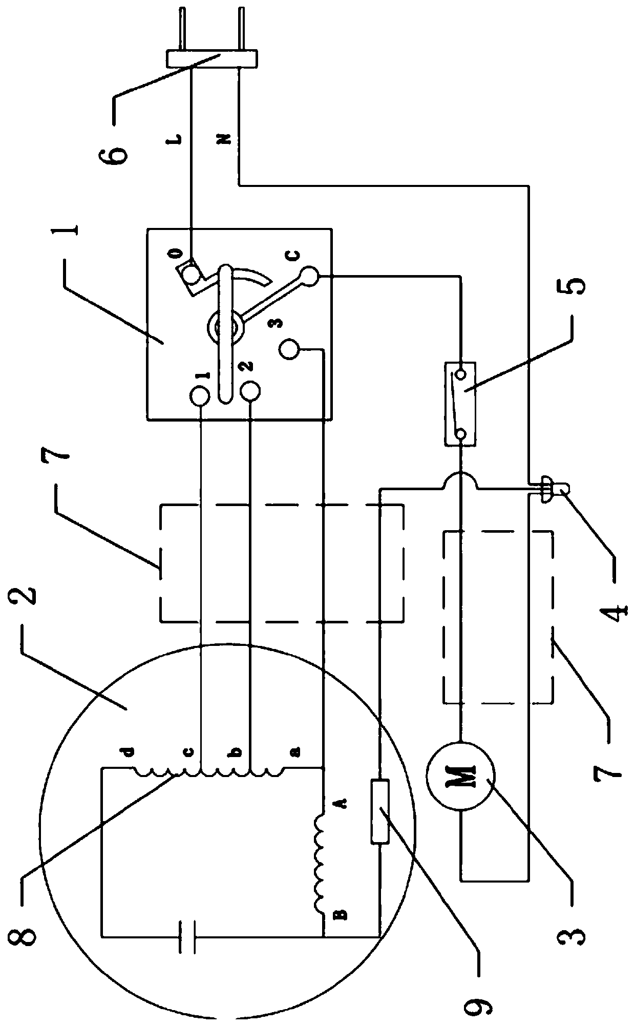
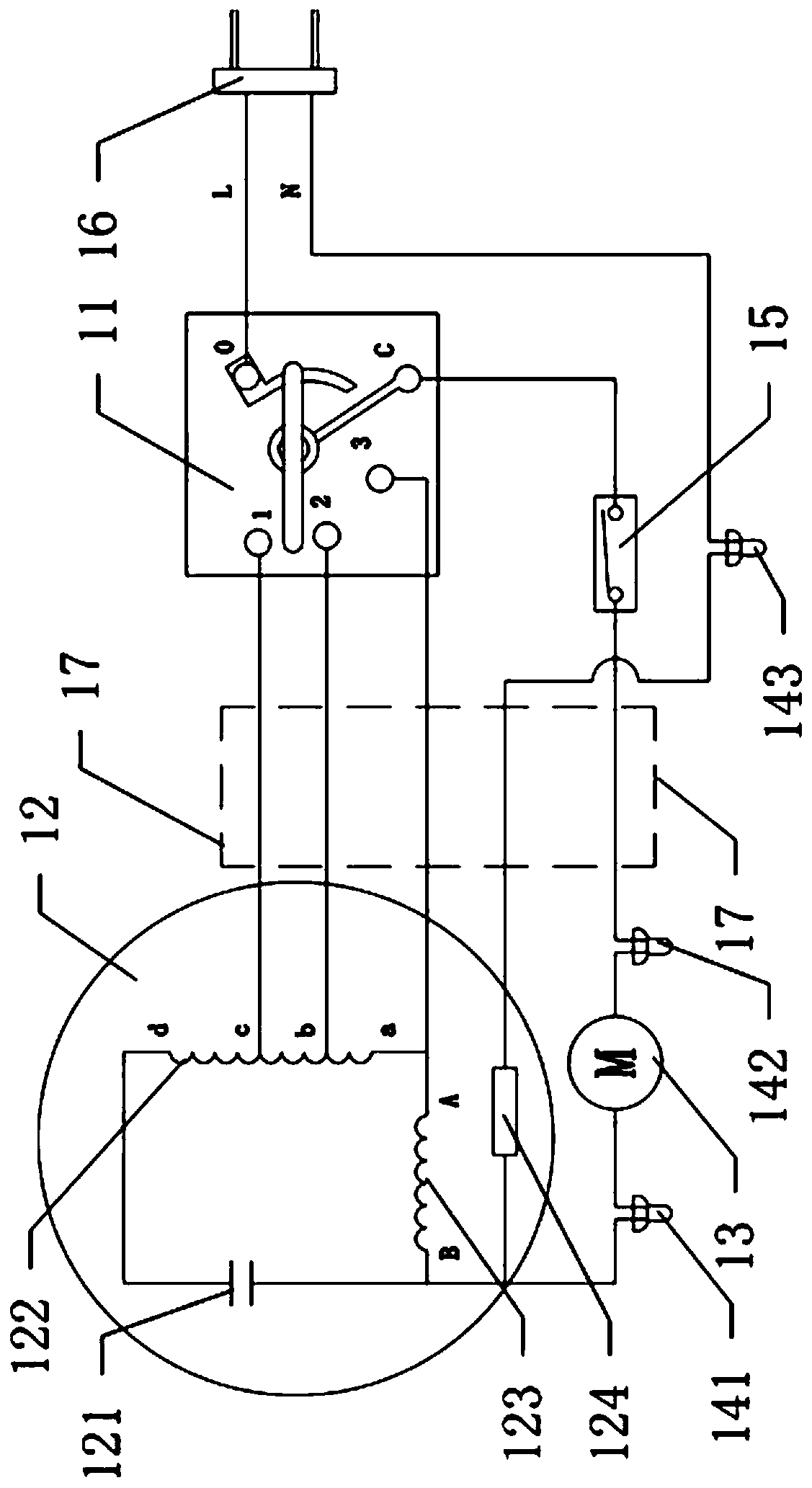
[0015] see figure 2 The present invention provides a wiring circuit for a wall fan motor, including a synchronous motor 13, a control switch 15, a multi-speed speed control switch 11, a live wire terminal L, a neutral wire terminal N, a capacitive motor 12, a first closed terminal 142, The second closed connection terminal 141 and the third closed connection terminal 143, wherein, the multi-speed static switching contacts of the multi-speed speed control switch 11 are connected to a plurality of input terminals of the ca...


PUM


Abstract

Provided is a wiring circuit of a wall fan motor. The device comprises a synchronous motor, a control switch, a multi-gear speed adjustment switch, a live wire end, a zero wire end, a capacitive motor, a first closed wiring terminal, a second closed wiring terminal and a third closed wiring terminal, characterized in that it is characterized in that it comprises, multi-gear static switching contacts of the multi-gear speed adjustment switch are sequentially and correspondingly connected to a plurality of input ends of the capacitive motor. The input end of the multi-gear speed adjustment switch is connected to the live wire end; one end of the synchronous motor is sequentially connected to the control switch and a synchronous motor connecting contact of the multi-gear speed adjustment switch through a first closed wiring terminal; the other end of the synchronous motor is connected to the input end of a thermal fuse of the capacitive motor through a second closed wiring terminal, and the output end of the thermal fuse of the capacitive motor is connected to the zero line end through a third closed wiring terminal. By changing the wiring mode of the synchronous motor and optimizingthe wiring circuit of the wall fan motor, in actual production, the number of sheaths can be reduced, wiring is simple, and the production efficiency is improved.

Description

technical field [0001] The invention relates to the technical field of wall fans, in particular to a wiring circuit for a wall fan motor. Background technique [0002] A wall fan refers to a small electric fan installed on the wall to save space. It is characterized by convenience, practicality and beauty. Wall fans are divided into two types: directional wall fans and steering wall fans. The steering wall fans can swing their heads to blow air, with a wide range of blowing and strong wind. Wall fans are mostly used in canteens, restaurants, factories and other places. [0003] In actual production, such as figure 1 As shown, the circuit part of the steering wall fan is mainly composed of a synchronous motor 3 for steering, a capacitive motor 2 for driving the blades to rotate, a multi-speed speed control switch 1, a control switch 5, and a power connector 6. The multi-speed speed control switch is operated to realize the working state of the capacitive motor, and then c...

Claims


Application Information

Patent Timeline
Patent Type & Authority Applications(China)
IPC IPC(8): H02P5/74H02H7/08
CPCH02P5/74H02H7/08H02H7/0805
Inventor 梅杰
Owner 佛山市深茂科技有限公司
Why Eureka
Try Eureka